


9
107600
OWNER’S MANUAL
For more information, visit www.desatech.com
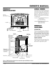
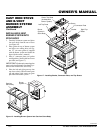
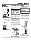
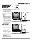
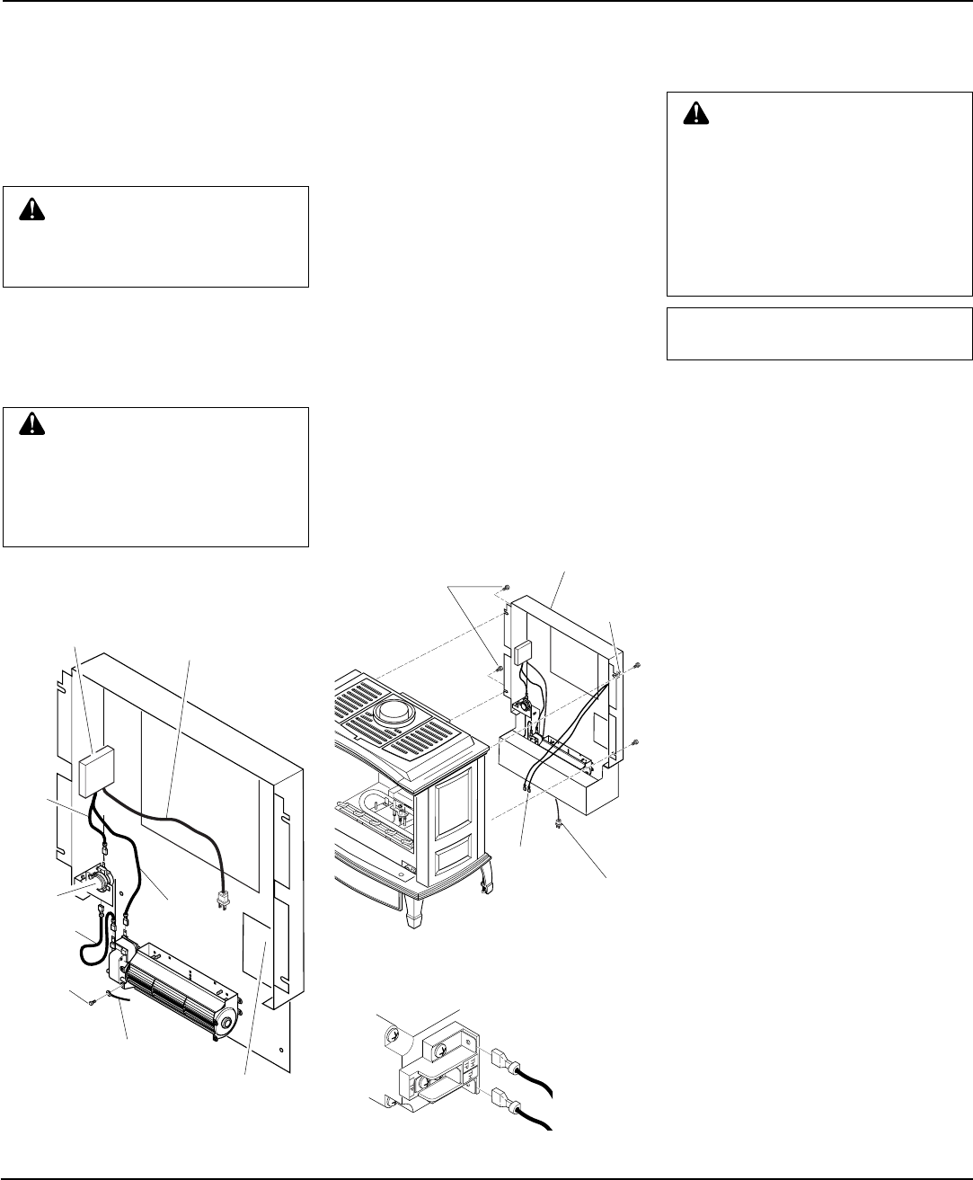
INSTALLING REAR COVER
1. Place rear cover behind stove body.
Rear cover will rest on the bottom ledge
of the stove body.
2. Place wire harness from ON/OFF
switch under the cast of stove body.
3. Using bolts provided, attach rear cover
to back of stove body. See Figure 21.
IMPORTANT:
This rear cover must be
securely in place before venting pipes
are installed.
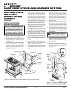
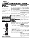
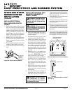
4. Open lower door panel. The valve is
attached to the underside of the burner
system assembly.
5. Connect one terminal of the wire from
ON/OFF switch to the THTP terminal
on the valve. Connect remaining wire
terminal to the TH terminal on the
valve. Make sure that the wire termi-
nals are in the positions on the unit as
pictured in Figure 22. If wires are not
connected as shown, the ON/OFF
switch will not work.
CAST IRON STOVE
AND B-VENT
BURNER SYSTEM
ASSEMBLY
Continued
WARNING: Failure to position
the parts in accordance with sup-
plied diagrams or failure to use
only parts specifically approved
with this heater may result in dam-
age or personal injury.
WARNING: A qualified in-
staller or service person must
connect burner system to gas
supply. Follow all local codes.
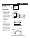
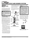
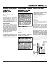
Figure 20 - Blower Wiring Layout
Green Ground Wire
Wiring Diagram Decal
Speed
Control
Box
Black
Wire
White
WireBlue Wire
Power Cord
(Route Through
Plastic Bushing in
Bottom Cover When
Assembled)
Screw
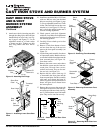
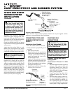
Figure 21 - Installing Rear Cover (Shown
with Optional Blower Accessory)
Rear Cover (Shown
with Optional Blower)
Hex
Bolts
15. Reattach bottom cover to rear cover
with 8 screws removed in step 2 on
page 8 (see Figure 18, page 8). Make
sure that you don’t pinch any wires
during reassembly.
Blower
Power
Cord
ON/OFF
Switch
Wire
Harness
ON/OFF
Switch
Figure 22 - Control Valve Terminals
To Control
Switch
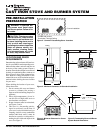
INSTALLATION PRECAUTIONS
Consult local building codes before begin-
ning the installation. Only a qualified ser-
vice person should install venting system.
The installer must follow these safety rules:
• Wear gloves and safety glasses for
protection
• Use extreme caution when using ladders
or when on roof tops
• Be aware of electrical wiring locations
in walls and ceilings
The following actions will void the war-
ranty on your venting system:
• Installation of any damaged venting
component
• Unauthorized modification of the vent-
ing system
• Installation of any component part not
manufactured or approved by DESA
International
• Installation other than as instructed by
these instructions
Your burner system is approved for use with
any listed gas vent. A listed gas vent is a factory
made and listed system designed, and installed
exclusively for removing products of combus-
tion, excess air, and dilution air resulting from
burning fuel gas. Metal vents, the most com-
mon type of vent, employ double wall con-
struction enclosing an insulating air space.
This air space both helps keep flue gases warm
and reduce heat transferred to nearby combus-
tibles. This appliance is equipped with a safety
control system designed to protect against
improper venting of combustion products.
VENTING
INSTALLATION
WARNING: Read all instruc-
tions completely and thoroughly
before attempting installation. Fail-
ure to do so could result in serious
injury, property damage, or loss of
life. Operation of improperly in-
stalled and maintained venting sys-
tem could result in serious injury,
property damage, or loss of life.
NOTICE: Failure to follow these
instructions will void the warranty.
Continued
Thermal
Switch