www.desatech.com
113109-01C 15
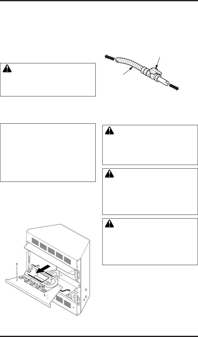
2. Remove screws that attach log base assembly
to replace (see Figure 23). Carefully lift up
log base assembly and remove from replace
(see Figure 23).
Note: If adding the G8005 series brick liner acces-
sory, install it now. Follow instructions in G8005
accessory kit.
3. Route gas line (provided by installer) from
equipment shutoff valve to replace. Route
exible gas supply line through one of the
access holes.
-
4. Attach the exible gas line to gas supply (see
Figure 24). Check tightness of exible gas
line attached to gas regulator of replace (see
Figure 24).
5. Check all gas connections for leaks. See
Checking Gas Connections.
INSTALLATION
Continued
Figure 23 - Removing Log Base
Assembly From Fireplace
Figure 24 - Attaching Flexible Gas Lines
Together
Flexible Gas Line
from Fireplace
Gas Regulator
To Fireplace Gas
Regulator
Equipment Shutoff Valve
Provided by Installer
To External
Regulator
Natural Gas
To Gas Meter
6. Replace log base assembly back into replace.
Feed exible gas line into replace base area
while replacing log base assembly. Make sure
the entire exible gas line is in replace base
area. Reattach log base assembly to replace
with screws removed in step 2.
and connections, internal and
external to unit, for leaks after
WARNING: Never use an
-
CAUTION: Make sure exter-
Connecting Fireplace to Gas
Supply
PRESSURE TESTING GAS SUPPLY
PIPING SYSTEM
1. Disconnect replace with its appliance main
gas valve (control valve) and equipment
shutoff valve from gas supply piping system.
Pressures in excess of 1/2 psig will damage
replace regulator.


