3
103451
OWNER’S MANUAL
PRODUCT
SPECIFICATIONS
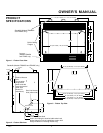
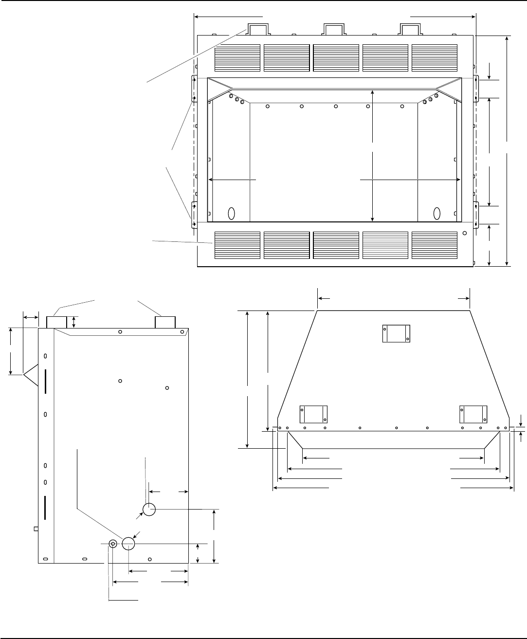
Figure 1 - Firebox Front View
Figure 2 - Firebox Side View
41 11/16" (36" models) • 47 11/16" (42" models)
36" (36" models) • 42" (42" models)
15 7/8"
35"
2 5/8"
2 5/8"
6 5/8"
19 3/8"
Built-in Nailing
Flanges
Standoffs (Models FB36NCA
and FB42NC only)
Louvers
(Models FB36CA
and FB42C only)
6 7/8"
1 1/2"
Diameter Holes
9 5/8"
8 7/16"
2 3/4"
1 1/2"
10 3/4"
13 9/16"
3 1/2"
Standoffs (Models FB36NCA and FB42NC only)
Electrical Access Hole
Strain relief fitting for electrical cable when hard
wiring firebox for built-in installations (strain relief
fitting included on circulating models only)
Gas Line Access
Hole (either side)
Electrical Access
Hole
(for use when
using blower
power cord with
external electrical
outlet. See
Blower Kit
Instructions)
Figure 3 - Firebox Top View
30 3/8" (36" Models) • 36 7/8" (42" Models)
42 3/8" (36" Models) • 48 3/8" (42" Models)
36" (36" Models) • 42" (42" Models)
41" (36" Models) • 47" (42" Models)
29 1/8" (36" Models) • 35 1/8" (42" Models)
19 1/2"
22 1/4"
5/8"


