


-8 - For more information, visit www.desatech.com
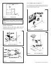
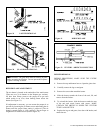
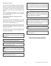
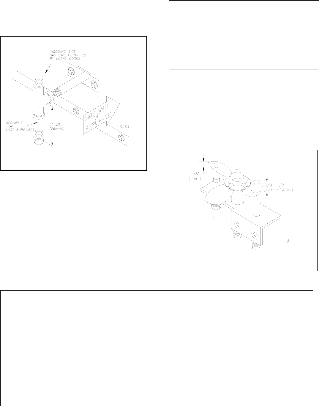
Install a sediment trap between the incoming gas line and the
gas control box (see figure 18). The sediment trap should
extend down a minimum of 3 inches (76 mm) beyond the
center of the pipe.
When routing gas line through conduit sleeve, make sure to
repack insulation to fill gaps between gas line and conduit
sleeve.
Compounds used on threaded joints of gas piping shall be
resistant to the action of propane or natural gas. Compounds
should be applied lightly to ensure excess sealant does not
enter the gas line.
Complete your gas line installation by connecting the
incoming gas line to flexible gas line. Secure tightly with a
wrench but do not over-tighten.
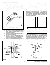
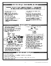
PILOT ADJUSTMENT
The pilot or electrode assembly is factory preset for the proper
flame height. Alterations to these settings may have occurred
during shipping and handling. If this is the case, some minor
readjustments may be necessary and should be done by a
qualified service technician. The proper settings for the
thermopile height should be at a distance of 3/8” (10mm) to
½” (13mm) from the pilot flame as shown in figure 19.
CAUTION: All gas piping and connections must be teste
d
for leaks after the installation is completed. After ensuring
that the gas valve is on, apply a commercial leak detectio
n
solution to all connections and joints. Bubbles forming
show a leak. Correct all leaks at once. DO NOT USE AN
OPEN FLAME FOR LEAK TESTING AND DO NOT
OPERATE ANY APPLIANCE IF A LEAK IS
DETECTED. LEAK TESTING SHOULD BE DONE BY
A QUALIFIED SERVICE PERSON.
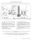
Figure 18 SEDIMENT TRAP
Figure 19 PILOT ASSEMBLY
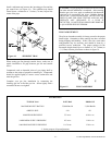
TYPE OF GAS NATURAL PROPANE
MAXIMUM INPUT RATING 35,000 Btu/Hr 31,500 Btu/Hr
ORIFICE SIZE #34 #51
MANIFOLD PRESSURE 3.5 in wc 10.0 in. wc
**MINIMUM SUPPLY PRESSURE 4.5 in wc 11.0 in. wc
**MAXIMUM SUPPLY PRESSURE 10.5 in wc 13.0 in. wc
GAS RATINGS
**
for the purpose of input adjustment