


10
201839
DIRECT-VENT PROPANE/LP GAS HEATER
DYNAVENT
®
INSTALLATION
(Continued)
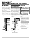
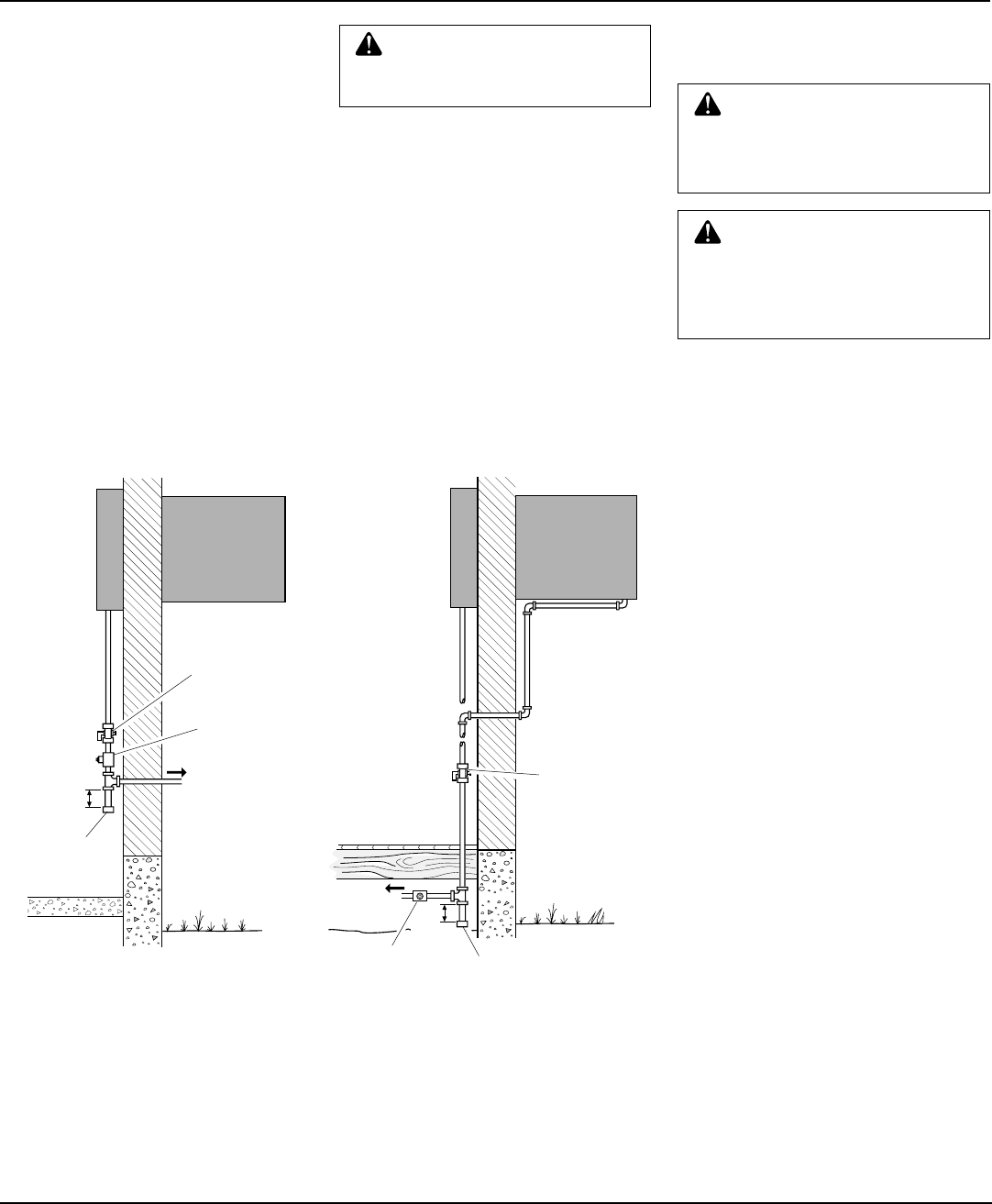
Installation must include an equipment
shutoff valve (supplied), ground joint union,
plugged 1/8" NPT tap, and a sediment trap.
Locate NPT tap within reach for test gauge
hook up. NPT tap must be upstream from
furnace (see Figure 15).
Install an equipment shutoff valve in an
accessible location. The equipment shutoff
valve is for turning on or shutting off the gas
to the appliance.
Apply pipe joint sealant lightly to male
threads. Prevent excess sealant from going
into pipe. Excess sealant in pipe could result
in clogged furnace valves.
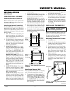
Install sediment trap in supply line as shown
in Figure 15. Locate sediment trap where it
is within reach for cleaning. A sediment trap
traps moisture and contaminants. This keeps
them from going into furnace controls. If
sediment trap is not installed or is installed
wrong, furnace may not run properly.
IMPORTANT:
Locate sediment trap where
trapped matter will not freeze. Install sedi-
ment trap in a vertical run of pipe. If gas
piping enters furnace from rear (outside),
you must locate sediment trap in crawl space
(see Figure 15). If you install furnace in
structure with slab foundation, you must
install gas piping to front of furnace (inside)
(see Figure 15).
CAUTION: Use pipe joint seal-
ant that is resistant to liquid pe-
troleum (LP) gas.
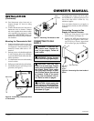
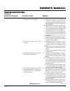
Slab Floor Installation
Equipment
Shutoff Valve
Test Gauge
Connection
To Gas Supply
3" Min.
Sediment
Trap
Gas Piping
Entering
Furnace
Front
(Inside)
Gas Piping
Entering
Furnace
Rear
(Inside)
To Gas Supply
Equipment
Shutoff
Valve
3" Min.
Sediment
Trap
Crawl Space Installation
Test Gauge
Connection
Figure 15 - Gas Connection
CHECKING GAS
CONNECTIONS
WARNING: Test all gas pip-
ing and connections for leaks
after installation or servicing.
Correct all leaks at once.
WARNING: Never use an open
flame to check for a leak. Apply a
mixture of liquid soap and water
to all joints. Bubbles forming show
a leak. Correct all leaks at once.
Pressure Testing Gas Supply
Piping System
Test Pressures In Excess Of 1/2 PSIG
(3.5 kPa)
1. Disconnect appliance with its appliance
main gas valve (control valve) and
equipment shutoff valve from gas
supply piping system. Pressures in
excess of 1/2 psig (3.5 kPa) will
damage heater regulator.
2. Cap off open end of gas pipe where
equipment shutoff valve was connected.
3. Pressurize supply piping system by either
using compressed air or opening main gas
valve located on or near gas meter.
4. Check all joints of gas supply piping
system. Apply mixture of liquid soap
and water to gas joints. Bubbles form-
ing show a leak.
5. Correct all leaks at once.
6. Reconnect furnace and equipment
shutoff valve to gas supply. Check re-
connected fittings for leaks.