


www.desatech.com
110098-01G
12
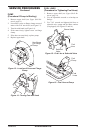
8. Inspect nozzle for damage. If damaged or
clogged, replace nozzle.
9. Make sure plug is in place on burner head.
10. Replace nozzle into burner head and tighten
firmly (175-200 inch-pounds).
11. Attach burner head to combustion chamber.
12. Install spark plug in burner head.
13. Attach spark plug wire to spark plug.
14. Attach fuel line to solenoid valve. Tighten
firmly.
15. Replace upper shell.
PUMP PRESSURE ADJUSTMENT
FOR HEATERS WITH FUEL FILTER/
CANISTER EXTERNAL TO PUMP
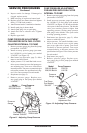
1. Remove pressure gauge plug from fuel pump
port marked “GAUGE.”
2. Install accessory pressure gauge (part num
-
ber 110380-01) to fuel pump port marked
“GAUGE” (see Figure 11).
3. Start heater (see
Operation, page 5). Allow
motor to reach full speed.
4. Adjust pressure. Use small flat blade screw
-
driver to turn slotted screw at fuel pump pres
-
sure adjusting port. Turn screw clockwise to
increase pressure. Turn screw counterclockwise
to decrease pressure. See specifications in Fig
-
ure 11 for correct pressure for each model.
5. Stop heater (see page 5).
6. Remove pressure gauge. Replace pres
-
sure gauge plug in fuel pump port marked
“GAUGE.”
SERVICE PROCEDURES
Continued
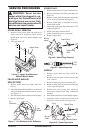
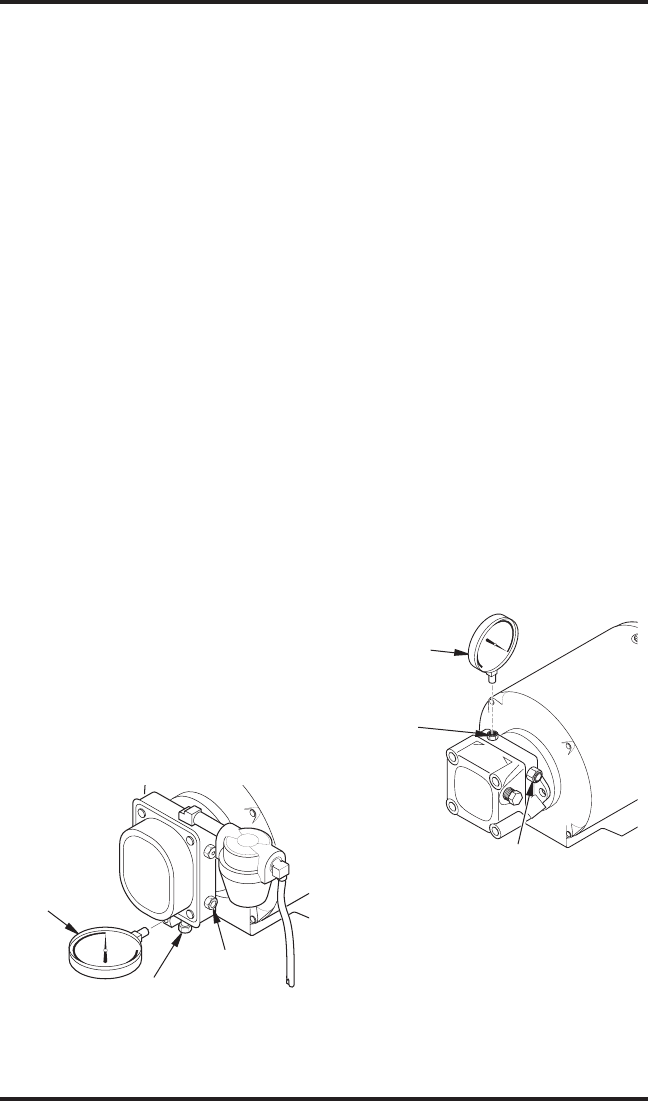
Figure 11 - Adjusting Pump Pressure
psi
Pressure
Gauge
Fuel Pump Port
Marked “GAUGE”
Fuel Pump
Port Marked
“PRESS ADJ”
Model Pump Pressure
350,000 Btu/Hr 100 PSI
600,000 Btu/Hr 110 PSI
PUMP PRESSURE ADJUSTMENT
FOR HEATERS WITH FUEL FILTER
INTERNAL TO PUMP
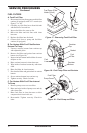
1. Remove pressure gauge plug from fuel pump
port marked “GAUGE.”
2. Install accessory pressure gauge (part num
-
ber 110380-01) to fuel pump port marked
“GAUGE” (see Figure 12). Do not use bleeder
valve port to check the pressure. The bleeder
valve port contains pressure higher than
operating pressure. Setting pump pressure
with gauge in the bleeder valve port results
in wrong operating pressure.
3. Start heater (see Operation, page 5). Allow
motor to reach full speed.
4. Adjust pressure. Use small flat blade screw
-
driver to turn slotted screw at fuel pump
port at top right side of pump. Turn screw
clockwise to increase pressure. Turn screw
counterclockwise to decrease pressure. See
specifications in Figure 12 for correct pressure
for each model.
5. Stop heater (see page 5).
6. Remove pressure gauge. Replace pres
-
sure gauge plug in fuel pump port marked
“GAUGE.”
psi
Pressure
Gauge
Fuel Pump
Port Marked
“GAUGE”
Pressure
Adjustment Port
Figure 12 - Adjusting Pump Pressure
Model Pump Pressure
350,000 Btu/Hr 100 PSI
600,000 Btu/Hr 110 PSI