


111739-01A
For more information, visit www.desatech.com
For more information, visit www.desatech.com
7
7
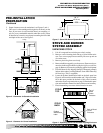
STOVE AND BURNER
SYSTEM ASSEMBLY
Continued
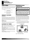
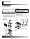
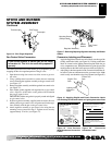
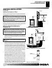
4. Thermostat Blower Only: Attach thermal switch and bracket
to inside rear cover wall with two hex head screws provided as
shown in Figure 10. After securing bracket to rear cover, care-
fully bend along existing bend line on bracket to almost a 90°
angle (see Figure 10). This will allow thermal switch to be
positioned against stove rear wall and sense temperature when
in operating mode.
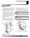
5. Place speed control on left inside of rear cover and push the
plastic control shaft through opening (see Figure 10).
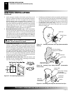
6. While supporting speed control, secure control shaft with lock nut
by pushing and turning lock nut with pliers clockwise until tight
against the side of rear cover. Place control knob provided onto shaft.
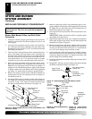
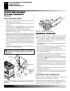
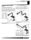
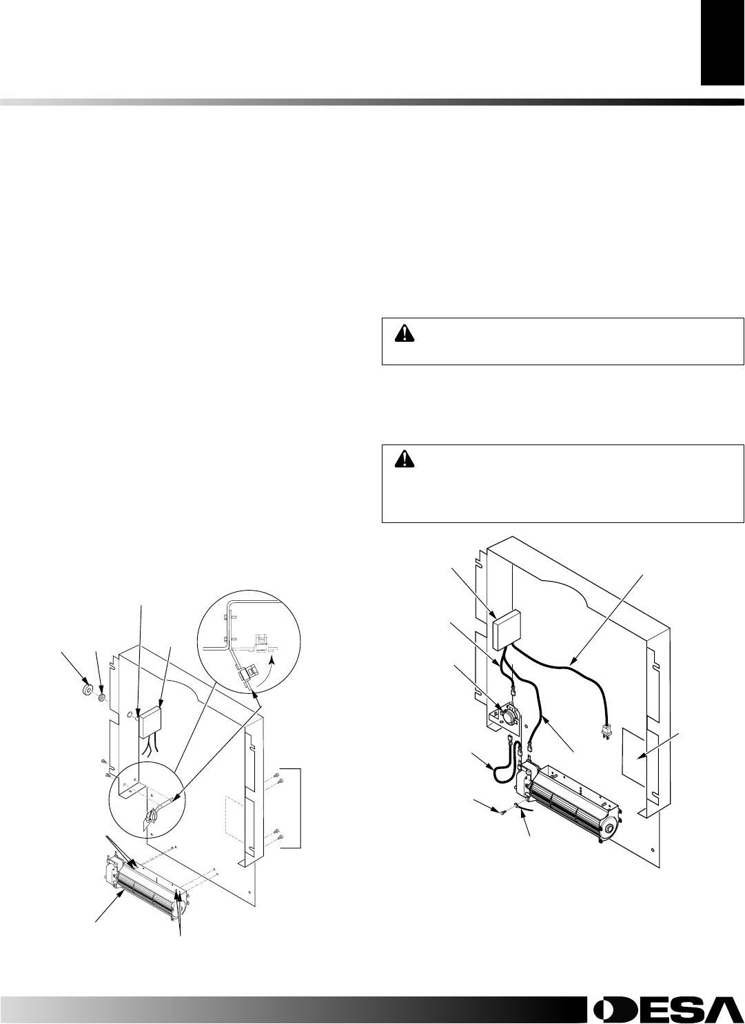
7. Place the green ground wire between the bottom hole on the
blower assembly and the hex screw and tighten (see Figure 11).
8. Connect the blue wire on the blower assembly to one side of
the thermal switch (see Figure 11).
9. Connect the black wire to the other side of the thermal switch
(see Figure 11).
10. Connect the white wire to the other terminal on the blower mo-
tor assembly (see Figure 11). Make sure the thermal switch has
been properly installed to fit against back of fireplace insert af-
ter the rear cover assembly has been reinstalled.
Green Ground Wire
Wiring
Diagram
Decal
Speed
Control
Black
Wire
White
Wire
Blue Wire
Power Cord (Route Through
Plastic Bushing in Bottom
Cover When Assembled)
Screw
Thermal
Switch
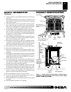
WARNING: Never touch the blower wheel while in
operation.
WARNING: Failure to position the parts in accor-
dance with supplied diagrams or failure to use only
parts specifically approved with this heater may result
in damage or personal injury.
Figure 11 - Blower Wiring Layout (Thermostat Blower Shown)
11. Make sure all wire connections to terminals on blower motor
and thermal switch are securely attached and that the screw
retaining the green ground wire is tight.
12. Check to make sure that the power cord is completely clear of the
blower wheel and that there are no foreign objects in blower wheel.
13. Peel off the backing paper and stick the supplied wiring dia-
gram decal on the inside of rear cover as shown (see Figure 11).
14. Reattach bottom cover to rear cover with 8 screws (see Figure
9, page 6). Make sure that you don’t pinch any wires during
reassembly. Route power cord through plastic bushing in bot-
tom of rear cover.
STOVE AND BURNER SYSTEM ASSEMBLY
Installing Optional Blower Accessory (Cont.)
Speed
Control
Blower
Control
Knob
Locknut
Thermal
Switch and
Bracket
Control
Shaft
TOP VIEW
Figure 10 - Blower Assembly, Speed Control, and Thermal
Switch Locations
Blower
Assembly
Mounting Holes
Screws
Mounting
Holes