


www.desatech.com
113101-01C
16
Pressure Testing Heater Gas
Connections
1. Open equipment shutoff valve (see Figure 15,
page 15).
2. Open main gas valve located on or near gas
meter for natural gas or open propane/LP
supply tank valve.
3. Make sure control knob of heater is in the
OFF position.
4. Check all joints from gas meter (natural gas)
or propane/LP supply to equipment shutoff
valve (see Figure 16 or 17, page 15). Apply
a commercial leak detection solution to all
joints. Bubbles forming show a leak.
5. Correct all leaks at once.
6. Light heater (see Operating Heater, page 18
[manually-controlled models] or page 21
[thermostatically-controlled models]). Check
all other internal joints for leaks.
7. Turn off heater (see To Turn Off Gas to Appli
-
ance, page 20 [manually-controlled models] or
page 22 [thermostatically-controlled models]).
INSTALLING LOGS, MODELS
CGS2718PA, CGS2718NA,
CGS3124PA, CGS3124NA,
SGS3124PA AND SGS3124NA
WARNING: Failure to position
the parts in accordance with these
diagrams or failure to use only
parts specifically approved with
this heater may result in property
damage or personal injury.
CAUTION: After installa-
tion and periodically thereafter,
check to ensure that no flame
comes in contact with any log.
With the heater set to High, check
to see if flames contact any log. If
so, reposition logs according to
the log installation instructions
in this manual. Flames contact
-
ing logs will create soot.
INSTALLATION
Continued
Each log is marked with a number. These numbers
will help you identify the log when installing. It
is very important to install these logs exactly as
instructed. Do not modify logs. Only use logs
supplied with heater.
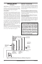
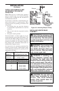
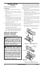
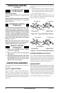
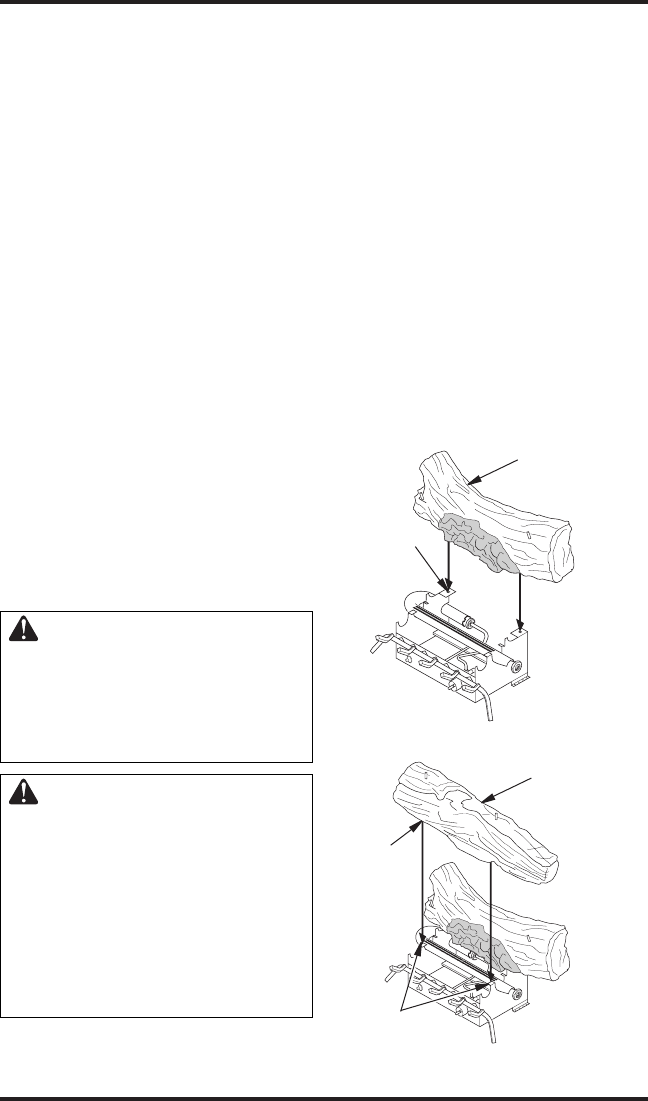
1. Locate pegs on the bottom of back log (#1).
Slide these pegs into the holes in the grate base
behind the burner (see Figure 18).
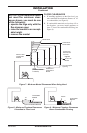
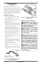
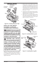
2. Locate the notches on the back of the front log
(#2). Slide these notches over the tabs of the
grate base (see Figure 19).
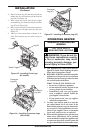
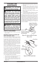
3. Locate the holes in the bottom of the left
crossover log (#3). Place crossover log on
pegs on left of the back log and front log (see
Figure 20, page 17).
4. Locate the holes in the bottom of the right
crossover log (#4). Place crossover log on
pegs on right of the back log and front log
(see Figure 20, page 17).
5. Add lava rock around base of heater if desired.
Do not place lava rock on logs or burner.
Figure 18 - Installing Back Log
Back Log (#1)
Hole
Figure 19 - Installing Front Log
Front
Log (#2)
Notch
Tabs of
Grate Base