


13
103414
OWNER’S MANUAL
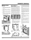
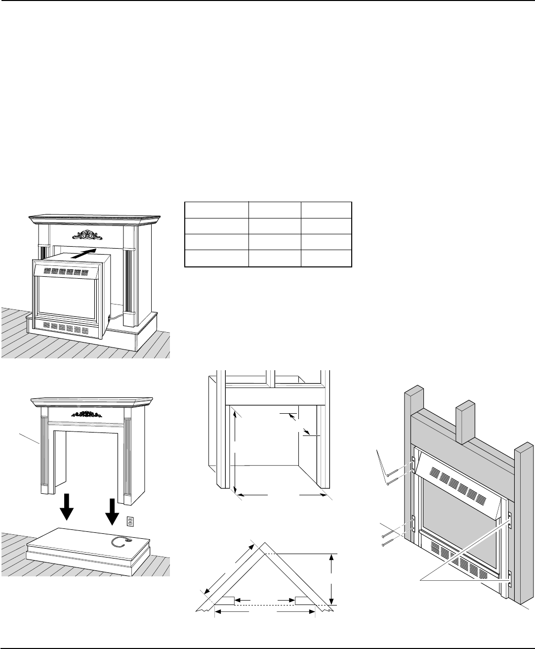
34 3/4"
17 3/4"
33"
39 3/8"
27 7/8"
55 5/8"
34 3/4"
INSTALLATION
Continued
9. If using an optional blower, install it
now. Follow instructions provided with
the blower.
10. Connect fireplace to gas supply (see
Connecting Fireplace To Gas Supply,
page 15).
11. Check all gas connections for leaks. See
Checking Gas Connections, pages 15
and 16.
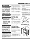
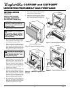
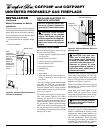
12. After heater is secured, replace mantel
on hearth base (see Figure 25). Make
sure mantel is flush against wall. In-
stall brass trim (see page 7).
Figure 24 - Inserting Fireplace Into Cabi-
net Mantel
Figure 25 - Installing Cabinet Mantel
Cabinet
Mantel
BUILT-IN FIREPLACE
INSTALLATION
(Check Local Building Codes)
Built-in installation of this fireplace involves
installing fireplace into a framed-in enclo-
sure. This makes the front of fireplace flush
with wall. An optional brass trim accessory
is available (see Accessories, page 32). The
brass trim will extend past the sides of the
fireplace approximately 1/2". This will cover
the rough edges of the wall opening. If
installing a mantel above the fireplace, but
you must follow the clearances shown in
Figure 29, page 14. Follow the instructions
below to install the fireplace in this manner.
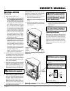
Actual Framing
Height 32
3
/8" 33"
Front Width 34
5
/16" 34
3
/4"
Depth 16
11
/16" 17
3
/4"
Continued
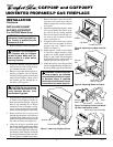
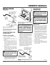
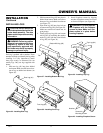
Figure 26 - Rough Opening for Installing
in Wall
1. Frame in rough opening. Use dimen-
sions shown in Figure 26 for the rough
opening.
If installing in a corner, use dimensions
shown in Figure 27 for the rough open-
ing. The height is 33" which is the same
as the wall opening in Figure 26.
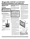
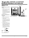
Figure 28 - Attaching Fireplace to Wall
Studs
2. If using optional blower, install it now.
Also install and properly ground
GA3555 three prong 120 volt outlet in
fireplace. Follow instructions included
in kits.
3. Install gas piping to fireplace location.
This installation includes an approved
flexible gas line (if allowed by local
codes) after the manual shutoff valve.
The flexible gas line must be the last
item installed on the gas piping. See In-
stalling Gas Piping to Fireplace Loca-
tion, page 14.
4. Carefully set fireplace in front of rough
opening with back of fireplace inside
wall opening.
5. Attach flexible gas line to fireplace gas
regulator. See Connecting Fireplace to
Gas Supply, page 15.
6. Carefully insert fireplace into rough
opening.
7. Attach fireplace to wall studs using
nails or wood screws through holes in
nailing flange (see Figure 28).
8. Check all gas connections for leaks. See
Checking Gas Connections, pages 15
and 16.
9. If using optional GA7090 Brass Trim
Kit, install brass trim after final finish-
ing and/or painting of wall (see Figure
6, page 7).
Figure 27 - Rough Opening for Installing
in Corner
Nailing
Flanges
Nails or
Wood
Screws