


12
103413
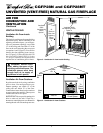
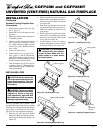
UNVENTED (VENT-FREE) NATURAL GAS FIREPLACE
CGFP28N and CGFP28NT
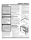
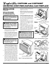
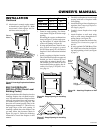
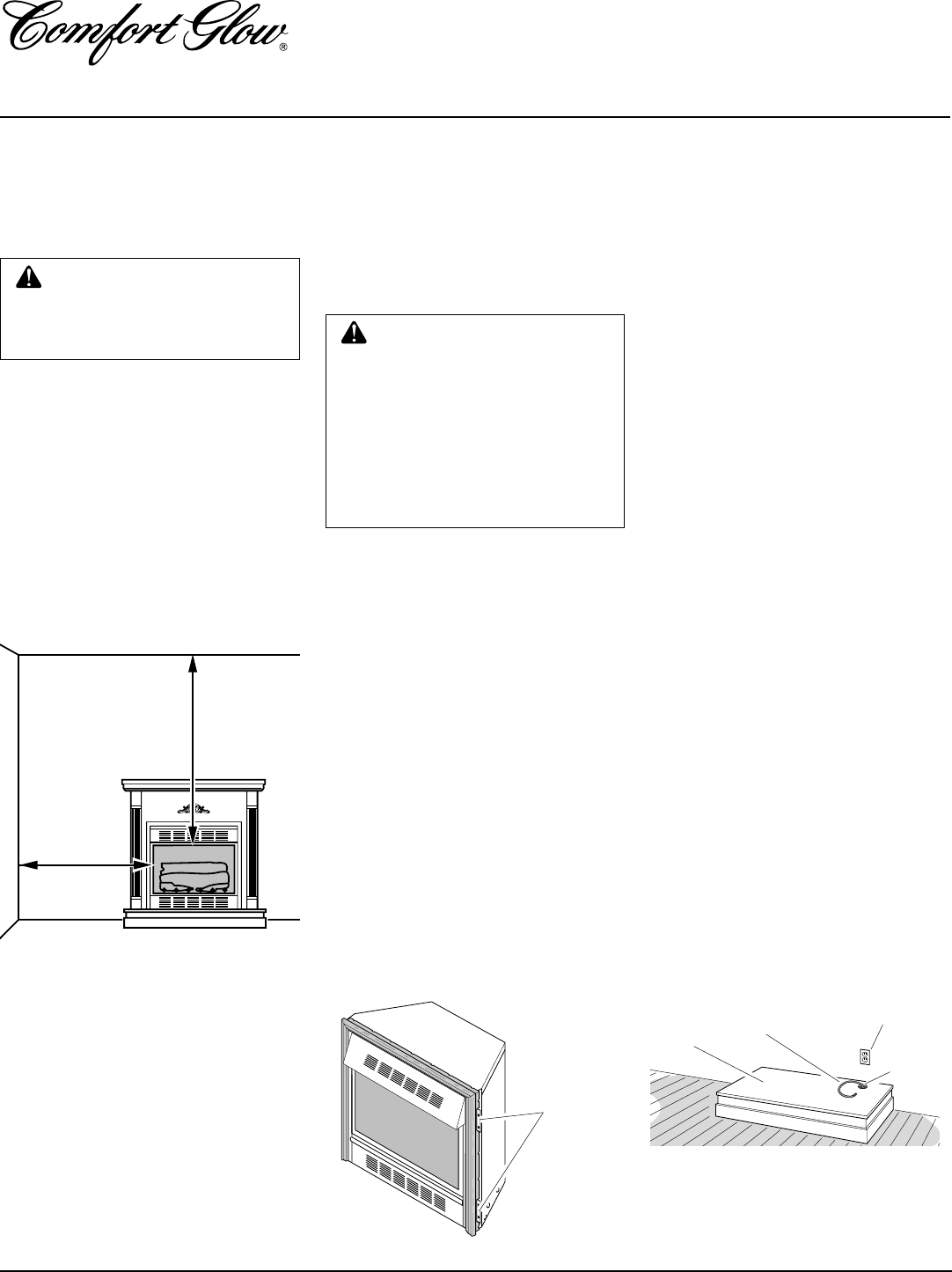
Figure 23 - Placing Hearth Base Accessory
Against Wall
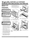
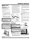
Figure 22 - Location of Nailing Flanges
INSTALLATION
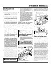
CLEARANCES
Note:
Clearances are the same if using
optional cabinet mantel or built-in
installation.
WARNING: Maintain the mini-
mum clearances. If you can, pro-
vide greater clearances from
floor, ceiling, and adjoining wall.
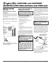
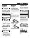
MINIMUM
CLEARANCE
Side Wall - 16 "
Ceiling - 42"
Floor - 0"
Carefully follow the instructions below. This
will ensure safe installation.
Minimum Wall and Ceiling
Clearances (see Figure 21)
A. Clearances from the side of the fire-
place opening to any combustible wall
should not be less than 16 inches for a
cabinet mantel or 12 inches for a cor-
ner installation.
B. Clearances from the top of the fireplace
opening to the ceiling should not be less
than 42 inches.
Note:
The instructions below show installa-
tion using the GMC11F/GMC12U/
GCM13F series cabinet mantel and the
GC3333F/GC3334U/GC3335F series
hearth base accessories (see Accessories,
page 25). A brass trim kit is included with
each mantel accessory. The hearth base ac-
cessory shown is optional for this installa-
tion. You can install fireplace and cabinet
mantel directly on the floor.
1. Assemble cabinet mantel, brass trim
kit, and hearth base. Assembly instruc-
tions are included with each accessory.
2. If installing an optional blower acces-
sory (see Accessories, page 25). Install
a properly grounded 120 volt, three
prong electrical outlet at fireplace lo-
cation if outlet is not there. If possible,
locate outlet so cabinet mantel will
cover it when installed (see Figure 23).
3. Break off nailing flanges (see Figure
22) with hammer or pliers.
WARNING: For conventional
installation, it is recommended
you use the cabinet mantel or
hearth bases specified in this
manual. Surface clearances may
not be sufficient with other cabi-
net mantels and hearth bases.
This may create a fire hazard. See
Accessories
, page 25, for correct
mantels and hearth bases.
Figure 21 - Minimum Clearance to Wall
and Ceiling
42"
16"
INSTALLATION
Continued
Nailing
Flanges
Electrical Outlet
Hearth
Base
Flexible Gas
Line
Gas
Line
Access
Hole
4. Place mantel and base in desired loca-
tion. Place heater in front opening of
mantel. Make sure all pieces fit prop-
erly. Remove mantel.
5. Mark floor and base or wall for gas line
entrance. Make sure there is enough
clearance between heater and mantel
for gas line.
IMPORTANT:
Make sure
there are no electrical lines where gas
piping will go through floor or wall.
6. Cut an access hole in hearth base top
to run flexible gas line to fireplace (see
Figure 23). Make sure to locate access
hole so cabinet mantel will cover it
when installed.
Note:
You can secure
base to floor using wood screws. Coun-
tersink screw heads and putty over.
7. Install gas piping to fireplace location.
This installation includes an approved
flexible gas line (if allowed by local
codes) after the manual shutoff valve.
The flexible gas line must be the last
item installed on the gas piping. See In-
stalling Gas Piping to Fireplace Loca-
tion, page 14.
8. Carefully place fireplace on top of
hearth base (Figure 24, page 13). Be
careful not to scratch or damage hearth
base.
Note:
You can secure fireplace to
hearth or floor. Open louver door. Lo-
cate screw holes in bottom of base.
Secure with wood screws through these
holes and into hearth or floor.
9. If using an optional blower, install it
now. Follow instructions provided with
the blower.
10. Connect fireplace to gas supply (see
Connecting Fireplace to Gas Supply,
page 15).
11. Check all gas connections for leaks. See
Checking Gas Connections, page 15.
CONVENTIONAL FIREPLACE
INSTALLATION
Conventional installation of this fireplace
involves installing fireplace along with the
cabinet mantel and hearth base accessory
against a wall in your home. Follow the
instructions below to install the fireplace in
this manner.