


9
105442
OWNER’S MANUAL
For more information, visit www.desatech.com
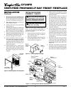
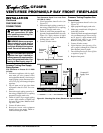
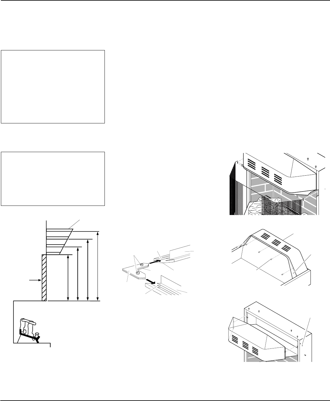
13"
16"
19"
21"
2
1
/2"
6"
8"
10"
Minimum Non-
Combustible
Material
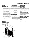
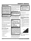
MANTEL CLEARANCES FOR
BUILT-IN INSTALLATION
Figure 8 - Minimum Mantel Clearances
for Built-In Installation
Mantel Shelf
INSTALLATION
Continued
Note:
All vertical
measurements
are from top of
fireplace
opening to
bottom of
mantel shelf.
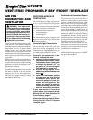
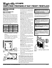
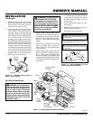
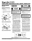
ASSEMBLING BRASS TRIM
(Brass trim shipped with mantel)
1. Remove packaging from three pieces
of brass trim.
2. Locate two adjusting plates with set
screws, and two shims in the hardware
packet.
3. Align shim under adjusting plate as
shown in Figure 9.
4. Slide one end of adjusting plate/shim
in slot on mitered edge of top brass trim
(see Figure 9).
5. Slide other end of adjusting plate/shim
in slot on mitered edge of side brass
trim (see Figure 9).
6. While firmly holding edges of brass
trim together, tighten both set screws
on the adjusting plate with slotted
screwdriver.
7. Repeat steps 1 through 6 for other corner.
8. Set brass assembly aside for later
installation.
REMOVING BRICK LINER
RETAINER
1. Using Phillips screw driver, remove 2
screws attaching brick liner retainers to
vertical sides.
2. Remove brick liner retainers and discard.
Replace 2 screws into vertical sides.
OPTIONAL MANTEL
INSTALLATION
Note:
Refer to instructions provided with
the mantel for assembly instructions. Refer
to instructions below for system installa-
tion. If using blower accessory (see Acces-
sories, page 28), see installation instruc-
tions on pages 10 and 11.
1
.
Choose location for fireplace and in-
stall gas supply line.
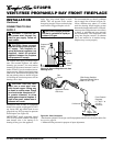
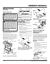
2. Remove screen from fireplace by re-
moving screws in each end of screen
rod (see Figure 10). Hold screen rod
cover while removing five hex head
screws underneath hood (see Figure
11). Carefully lift and pull out hood (see
Figure 12).
3. Assemble brass trim kit. See Assem-
bling Brass Trim, column 2.
Continued
Figure 11 - Removing Hood Screws
Hood
Screen
Rod
Cover
Screw
Figure 12 - Removing Hood
Mantel Screw
Location
Figure 10 - Removing Screen
Figure 9 - Assembling Brass Trim
Top
Brass
Trim
Side
Brass
Trim
Mitered
Edge
Shim
Set Screws
Adjusting
Plate
Slot
Slot
NOTICE: If your installation does
not meet the minimum clearances
shown, you must do one of the
following:
• raise the mantel to an accept-
able height
• remove the mantel
NOTICE: Surface temperatures of
adjacent walls and mantels be-
come hot during operation. Walls
and mantels above the firebox
may become hot to the touch. If
installed properly, these tempera-
tures meet the requirement of the
national product standard. Fol-
low all minimum clearances
shown in this manual.
If placing mantel above built-in fireplace,
you must meet minimum clearance between
mantel shelf and top of fireplace opening.