


11
105442
OWNER’S MANUAL
For more information, visit www.desatech.com
INSTALLATION
Continued
WARNING: A licensed electri-
cian must connect the wiring har-
ness to electrical supply follow-
ing all local codes. Electrician
must provide a clamp on the box
cover to secure the wiring. Wir-
ing should be routed through the
bushing in the hole on the outer
casing of heater.
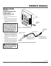
1. Install a snap bushing found in hard-
ware kit into one of the holes found on
rear of blower control shield. The other
hole is for a strain relief clamp (not sup-
plied) to secure incoming electrical
supply.
2. Follow steps 2 through 6 in Installing
Blower Assembly, page 10. Also re-
move black wire from middle/OFF
switch terminal.
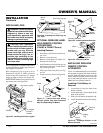
3. Remove black plastic strain relief and
power cord from switch plate (see Fig-
ure 17). The power cord supplied will
not be used in built-in installations. Pop
in the plastic snap bushing found in hard-
ware kit into the hole left by supply cord/
strain relief.
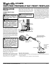
For Built-In Installation
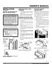
Figure 17 - Installing Blower Bracket Assembly
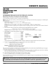
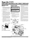
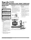
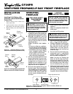
Figure 18 - Wiring Diagram For Fan
Accessory Built-In Installation
Continued
Blower
Control
Shield
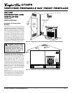
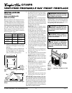
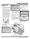
Figure 16 - Installing Switch Plate to
Blower Control Shield
Switch
Plate
Screw
9. Reconnect red wire to the AUTO switch
position. Reconnect blue wire to the ON
switch position. Reconnect green and
white wires to the power cord.
10. Install the switch plate on the blower
control shield with 2 - #10 screws pro-
vided (see Figure 16). Route power cord
out of the cabinet by inserting it through
the bushing on the outer casing (see Fig-
ure 15). Plug fan kit into 120-Volt
grounded power supply and test opera-
tion.
Note:
When switch is in the AUTO
position, the fan will start after the heater
has run for a few moments. The fan will
continue to run for several moments af-
ter the heater has been turned off. When
switch is in the ON position, the fan will
run until turned to OFF. Reinstall hood
assembly and close lower louver door.
11. Place log set back on the unit.
AUTO
OFF
O
N
Blower Bracket
Assembly
Screw
Wire
Harness
Power
Cord
Blower
Control
Shield
Shield
Cover
Wire
Harness
Switch
Plate
Switch
Clamp
Connector
(not included)
Outlet
Receptacle
Blue
Red
Strain
Relief
4. A licensed electrician must follow the
wiring diagram in Figure 18 to connect
incoming electrical supply to fan kit
wiring harness.
5. Test to make sure the blower is work-
ing properly.
6. Reinstall hood assembly (see page 9)
and close lower louver door.
7. Place log set back on the unit.
If any of the original wire as supplied with the appliance must be
replaced, original replacements must be used. DESA part no.
104015-01 (105°C) for power cord, and DESA part no. 103968-
01 (200°C) for wire harness.
101584-06
120 Vac. 60 Hz. .30 Amps
DESA International, Bowling Green, KY
Red
Red
Fan Switch
(Auto/Off/On)
Blue
Blue
Thermostat
Switch
(N.O.)
Green
White
Green
White
On
110/115
V.A.C.
Blower
Motor
Black
Off
1
2
3
Auto
WARNING: Never attempt to service heater while it is
plugged in, operating, or hot. Burns and electrical shock
could result. Only a qualified service person should ser-
vice or repair heater.
WARNING: Label all wires prior to disconnection
when servicing controls. Wiring errors can cause im-
proper and dangerous operation. Verify proper opera-
tion after servicing.
WARNING: ELECTRICAL
GROUNDING INSTRUCTIONS
This appliance is equipped with a
three-prong (grounding) plug for
your protection against shock
hazard and should be plugged
directly into a properly grounded
three-prong receptacle.