


- 12 - For more information, visit www.desatech.com
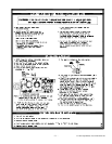
CONVERSION KIT
This conversion kit is packaged with the unit. Please check
the contents before beginning this conversion.
• Before proceeding, make sure the gas control valve is
in the “OFF” position and all electrical power to the
appliance is turned off.
• Wait five minutes to clear out any gas. Smell for any
gas odor especially near the floor. If any gas odor is
present, STOP! Refer to the lighting instructions
included in this manual.
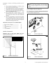
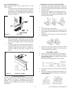
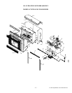
• Locate the latch on the louver assembly. Remove the
top and bottom louver by pulling the spring latches
toward the center of the fireplace simultaneously
until they are disengaged from the locating holes.
• Undo the latches located on the top and bottom side
of the firebox and swing the door to the fully open
position.
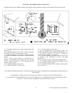
• Carefully remove the log set and the ceramic fiber
embers from the burner and place them outside the
combustion chamber.
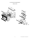
• Replace the main burner orifice with the burner
orifice included in the conversion kit (Model CD42M
contains two burner orifices).
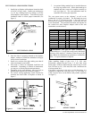
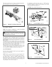
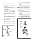
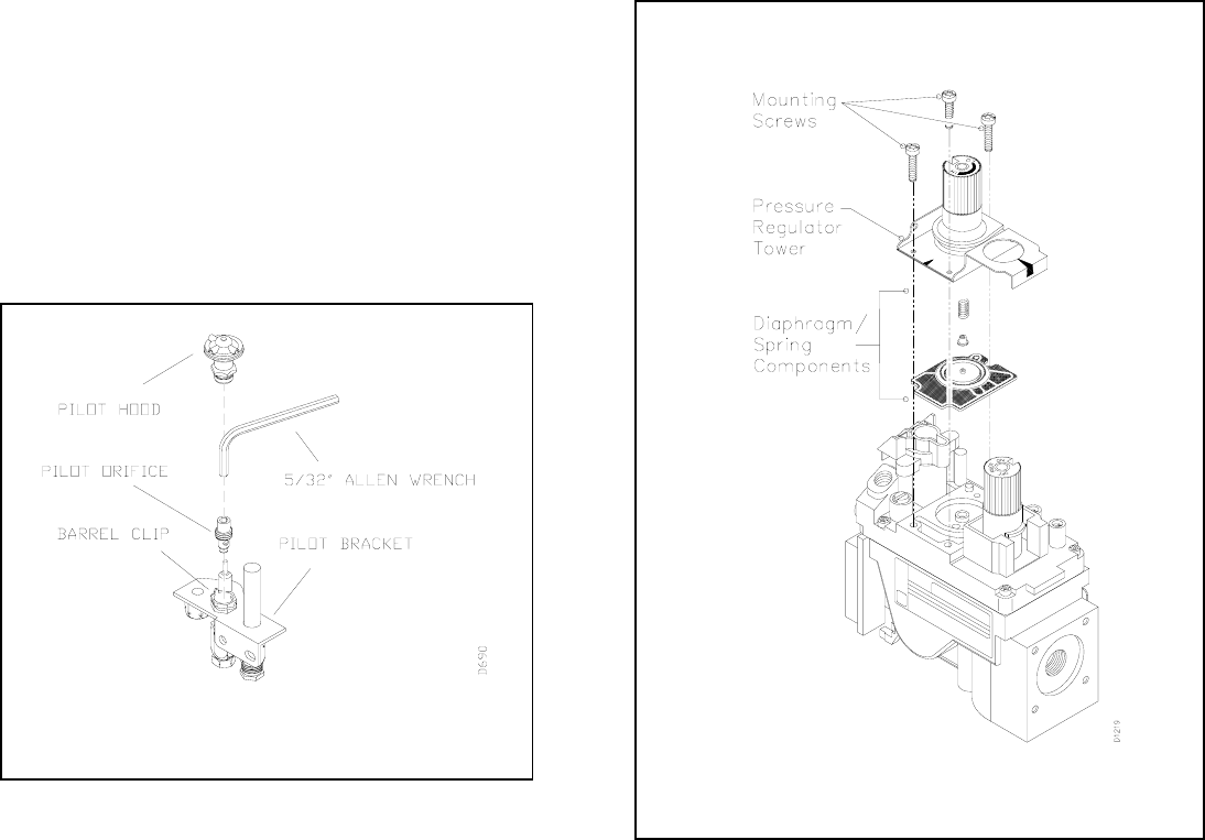
• Remove the pilot hood by pulling up until it
disengages from the barrel. Do not remove the
retainer clip (see figure 21).
• Remove the pilot orifice from inside the barrel using
a 5/32” allen wrench to unscrew the orifice.
• Replace pilot orifice with LP orifice supplied with
this kit. The number 30 is stamped on the sleeve for
identification. Insert the small end of the new pilot
orifice into the barrel and thread until tight with the
allen wrench.
• Line up the notch on pilot hood to the positioning tab
on the barrel receiver and snap back into position.
IMPORTANT: Be careful not to bend or kink the aluminum
tubing during conversion. Make sure the pilot hood and orifice
are properly mated and aligned after finishing this conversion.
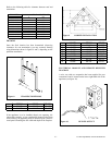
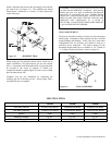
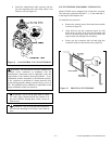
Convert the gas control valve by swapping out the valve
regulator portion of the gas valve.
• Using a TORX T20 or a slotted screwdriver, remove
and discard the three mounting screws, pressure
regulator tower, and diaphragm/spring components
(see figure 22).
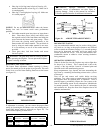
• Insure that the rubber gasket is properly positioned
on the new pressure regulator assembly. Install the
new pressure regulator assembly to the valve using
the new mounting screws supplied with the kit.
Tighten the screws securely (approximately 25in-
lbs.) (see figure 23).
Figure 21 PILOT ORIFICE
Figure 22 GAS CONTROL VALVE CONVERSION