


111161-01A
18
For more information, visit www.desatech.com
For more information, visit www.desatech.com
OPERATING HEATER
Optional Remote Operation (Cont.)
INSPECTING BURNERS
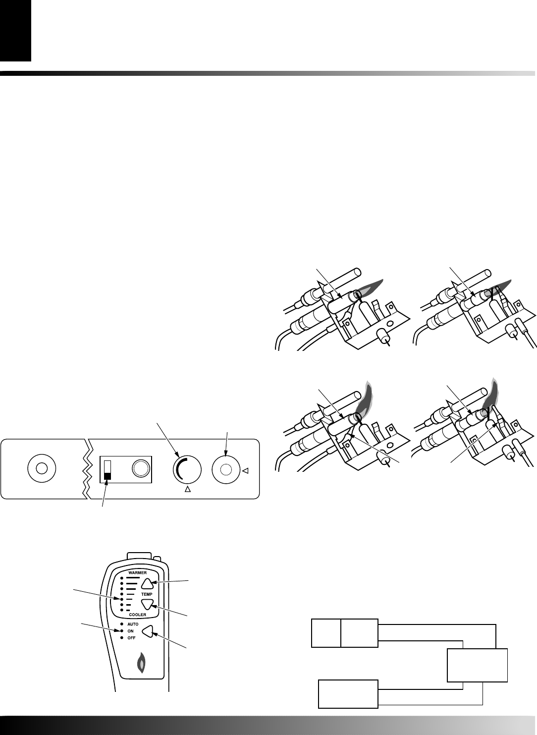
Pilot Flame Pattern
Main Burner
WIRING DIAGRAM
CGHRCTA Series Operation:
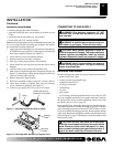
2b. Press the AUTO/ON/OFF button on the hand-held remote
control (see Figure 35). The lights to the left of the button
will show AUTO, ON, or OFF.
• In the ON mode, the burners will ignite. The heater is in
manual mode when ON is lit.
• In the AUTO mode, the thermostat in the hand-held re-
mote unit controls the room temperature. To increase the
room temperature, press the top arrow of the TEMP but-
ton. To lower the room temperature, press the bottom
arrow of the TEMP button. At higher settings the heater
will run longer.
IMPORTANT:
This remote control has been specially
engineered to take an air temperature sample every 5.5
minutes in the auto mode. It will not respond immedi-
ately to the temperature setting being turned up or down.
IMPORTANT:
The hand-held remote control unit must
be near the heater. Do not keep the hand-held remote
control unit too close to the heater. The thermostat on
the hand-held remote control unit will heat up too quickly
and turn the heater off.
3. To turn the burner off, press the AUTO/ON/OFF button
until OFF lights. The pilot will remain lit.
IMPORTANT:
To turn the pilot off, manually turn the con-
trol knob on the heater to the OFF position.
OPERATING HEATER
Continued
ON
OFF
REMOTE
O
F
F
P
I
L
O
T
O
N
L
O
I
H
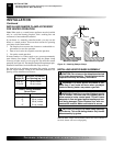
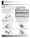
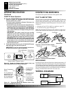
Figure 34 - Setting the Selector Switch, Control Knob, and
Flame Adjustment Knob for Remote Operation
Selector Switch in Remote Position
Control Knob
in On Position
Flame Adjustment
Knob
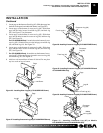
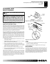
Increases Room
Temperature in
AUTO Mode
Decreases Room
Temperature in
AUTO Mode
Turns Burner On
or Off and Allows
You to Choose
the Auto Setting
Shows Temperature
Setting
The Log Heater will
Automatically Cycle
between Pilot and
the Heat Setting that
has been Selected
Figure 35 - Thermostat Hand-Held Remote Control Unit
Selections (CGHRCTA Series Only)
INSPECTING BURNERS
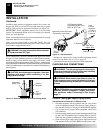
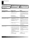
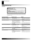
Check pilot flame pattern and burner flame patterns often.
PILOT FLAME PATTERN
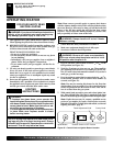
Figure 36 shows a correct pilot flame pattern. Figure 37 shows an
incorrect pilot flame pattern. The incorrect pilot flame is not
properly heating the thermocouple. When the thermocouple cools,
the heater will shut down.If pilot flame pattern is incorrect, as shown
in Figure 37
• turn heater off (see To Turn Off Gas to Appliance, page 17)
• see Troubleshooting, pages 20 through 22
Note:
The pilot flame on natural gas units will have a slight curve,
but the flame should be blue and have no yellow or orange color.
Figure 36 - Correct Pilot Flame Pattern
Figure 37 - Incorrect Pilot Flame Pattern
Pilot Burner
Pilot Burner
Thermocouple
Pilot Burner
Pilot Burner
MAIN BURNER
Periodically inspect all burner flame holes with the heater running. All
slotted burner flame holes should be open with yellow flame present.
All round burner flame holes should be open with a small blue flame
present. Some burner flame holes may become blocked by debris or
rust, with no flame present. If so, turn off heater and let cool. Remove
blockage, blocked burner flame holes will create soot.
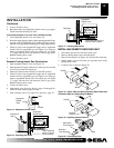
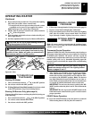
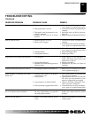
WIRING DIAGRAM
Receiver
Black
On
Off
Remote
Red
Red
White
Thermopile
Gas Control
TPTH TH
TPTH
TP
Propane/LP Gas
Natural Gas
Propane/LP Gas
Natural Gas