


111161-01A
13
13
For more information, visit www.desatech.com
For more information, visit www.desatech.com
INSTALLATION
Continued
5. Correct all leaks at once.
6. Reconnect heater and equipment shutoff valve to gas supply.
Check reconnected fittings for leaks.
Test Pressures Equal To or Less Than 1/2 PSIG (3.5 kPa)
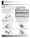
1. Close equipment shutoff valve (see Figure 15).
2. Pressurize supply piping system by either opening propane/LP sup-
ply tank valve for propane/LP gas or opening main gas valve lo-
cated on or near gas meter for natural gas, or using compressed air.
3. Check all joints from propane/LP supply tank to equipment
shutoff valve for propane/LP gas (see Figure 16) or from gas
meter to equipment shutoff valve for natural gas (see Figure
17). Apply noncorrosive leak detection fluid to gas joints.
Bubbles forming show a leak.
4. Correct all leaks at once.
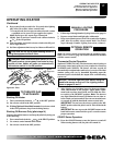
Pressure Testing Heater Gas Connections
1. Open equipment shutoff valve (see Figure 15).
2. Open propane/LP supply tank valve or main gas valve located
on or near gas meter for natural gas.
3. Make sure control knob of heater is in the OFF position.
4. Check all joints from propane/LP supply tank to equipment
shutoff valve for propane/LP gas (see Figure 16) or from gas
meter to equipment shutoff valve for natural gas (see Figure
17). Apply noncorrosive leak detection fluid to gas joints.
Bubbles forming show a leak.
5. Correct all leaks at once.
6. Light heater (see Operating Heater, pages 16 through 18).
Check all other internal joints for leaks.
7. Turn off heater (see To Turn Off Gas to Appliance, page 17).
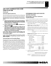
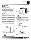
Figure 15 - Equipment Shutoff Valve
O
POSI
T
P
O
Open
Closed
Equipment
Shutoff
Valve
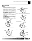
Figure 16 - Checking Gas Joints
Propane/LP
Tank
Equipment
Shutoff Valve
Thermostat Gas
Valve or Control
Valve Location
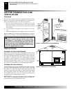
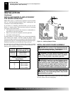
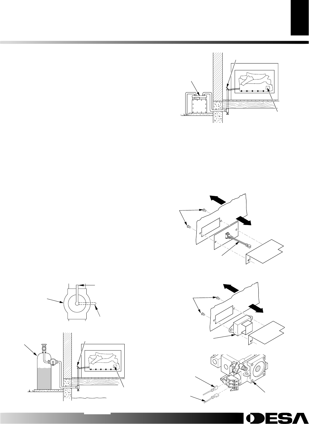
Figure 17 - Checking Gas Joints
Gas Meter
Equipment
Shutoff Valve
Thermostat Gas Valve or
Control Valve Location
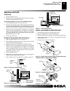
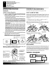
INSTALLING REMOTE RECEIVER UNIT
1. Disconnect switch wires from the control valve.
2. Remove phillips head screws and heat shield.
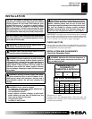
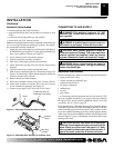
3. Remove switch plate (see Figure 18). Discard after removing.
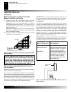
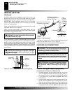
4. Install remote receiver unit onto gas log heater base using
phillips head screws.
5. Connect wires as shown in Figure 20.
Front
Back
Front
Back
Figure 18 - Switch Plate and Wiring Harness (Switch Plate and
Orientation May Vary Depending On Model)
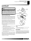
Figure 19 - Installing Remote Receiver
Wires
Screws
Remote
Receiver
Screws
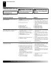
Valve
White Wire
From Receiver
Figure 20 - Connecting Wires
Red Wire
From Receiver
INSTALLATION
Checking Gas Connections (Cont.)
Installing Remote Receiver Unit