


www.desatech.com
901746-01E 9
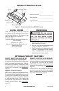
Installation and Gas Connection
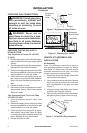
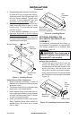
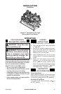
1. Place burner pan assembly in center of
replace oor. Make sure inlet end of pan
faces gas supply.
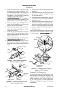
2. Thread gas supply tting to replace gas
supply pipe. Use thread sealant.
3. Install adapter tting onto burner inlet t-
ting using thread sealant on male threads
of burner inlet tting (see Figure 6). Adjust
to most convenient position.
4. Install gas connector tube to gas supply
tting. Carefully shape tube to attach to
adapter tting. Be careful not to cause
kinks in tube.
INSTALLATION
Continued
5. Using thread sealant (resistant to the action
of propane/LP gas) on larger end of tting,
screw the burner inlet tting through hole
and into burner manifold. Tighten using
a wrench. If using propane/LP gas, see
Propane/LP Gas Conversion, page 10.
6. Using burner clamp, screw, and nut pro-
vided, assemble clamp to pan (“U” style
burners only). This will hold the burner
manifold in place.
7. If using optional GA9050A-1 kit, go to
Optional GA9050A-1 On/Off Safety
Valve/Pilot Kit Assembly for installation
instructions. If using optional GA9150A
kit, follow instructions included with kit for
installation and operation.
Figure 8 - Installing Burner
Burner Clamp
Nut
Burner
Manifold
Burner Inlet
Fitting
Screw
Burner
Pan
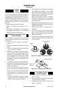
Figure 9 - Installing Burner
Adaptor Fitting
Gas
Connector
Tube
Burner Pan
Assembly (Facing
Front of Fireplace)
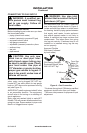
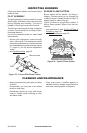
OFF SAFETY VALVE/PILOT KIT
For additional convenience and safety, or
for propane/LP conversion, an optional ON/
OFF safety valve/pilot kit is available. See
Accessories, page 19.
WARNING: You must use a
Natural Gas Installation
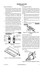
1. Thread the gas control valve onto the
burner inlet tting (see Figure 10). Use
thread sealant on the male threads of the
burner inlet tting. Hold the burner inlet
tting with a wrench to prevent overtight-
ening the connection to the burner. Make
sure the control rod is facing the front (see
Figure 10).
Figure 10 - Installing Gas Control Valve
Gas
Control
Valve
Control Rod
Burner Inlet
Fitting
Burner Pan
Assembly