


102370-01K
7
7
For more information, visit www.desatech.com
For more information, visit www.desatech.com
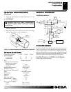
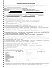
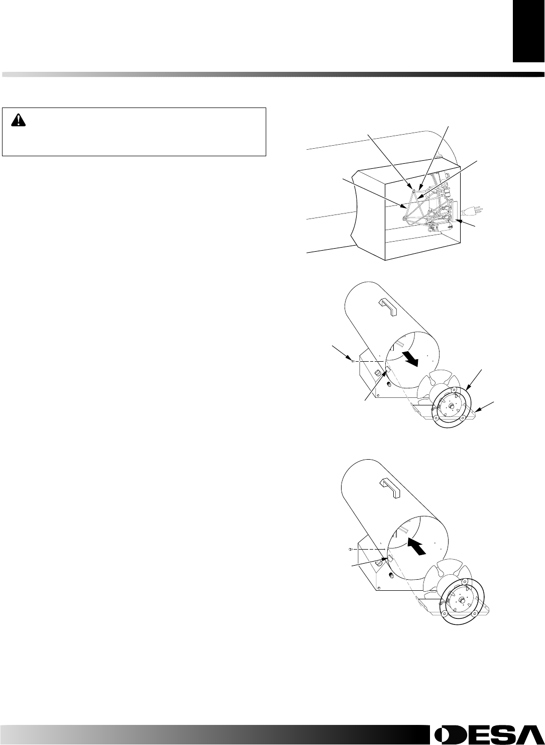
SERVICE PROCEDURES
MOTOR
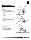
1. With heater on its side, remove base tray.
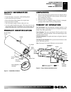
2. Access ground screw through underside of heater base. Re-
move ground screw. Disconnect the green motor wire and the
green power cord wire from underside of shell (see Figure 5).
3. Remove black and white motor wires from terminal board (see
Figure 5).
4. Carefully push motor wires through hole in bottom of shell.
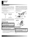
5. Remove screws holding motor mount to shell. Use nut-driver
(see Figure 6).
6. Carefully pull motor and fan out of shell.
IMPORTANT:
Be
careful not to damage fan. Do not set motor and fan down with
the weight resting on fan. This could damage fan pitch.
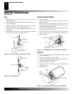
7. Use hex wrench to loosen setscrew which holds fan to motor
shaft.
8. Remove fan. Be careful not to damage the fan blade pitch.
9. Use nut driver to remove two nuts that attach motor to mo-
tor mount.
10. Discard old motor.
11. Attach motor to motor mount with two nuts. Tighten nuts firmly.
12. Replace fan on motor shaft. Make sure set screw contacts flat
surface on motor shaft.
13. Tighten set screw firmly (40-50 inch-pounds).
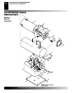
14. Carefully route motor wires through hole in shell (see Figure 7).
Place motor, motor mount, and fan guard into rear of heater shell.
15. Insert screws through heater shell and into motor mount.
Tighten screws firmly.
16. Turn heater on its side to access opening in bottom of base.
Connect green wires from motor, transformer, and power cord
to heater shell using ground nut (see Figure 5).
17. Attach black and white wires to terminal board (see Wiring
Diagram, page 9, for correct locations) .
18. Replace base tray.
WARNING: Never service heater while it is plugged
in, connected to propane supply, operating, or hot.
Severe burns and electrical shock can occur.
Ground
Screw
Terminal
Board
Motor
Green
Lead
Power Cord
Green Lead
Transformer
Green Lead
Figure 6 - Removing Motor, Motor Mount, and Fan Guard from
Heater
Figure 5 - Location of Ground Screw
Hole in Shell
for Wires
Motor
Mount
Screw
Fan
Guard
Motor
Mount
Figure 7 - Replacing Motor, Motor Mount, and Fan Guard into
Heater
Hole in
Shell for
Wires
SERVICE PROCEDURES