


10 116170-01A
www.desatech.com
SERVICE PROCEDURES
WARNING: To avoid risk of
burn and electrical shock, never
attempt to service heater while it
is plugged in, operating or hot.
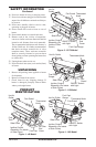
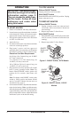
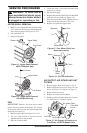
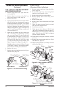
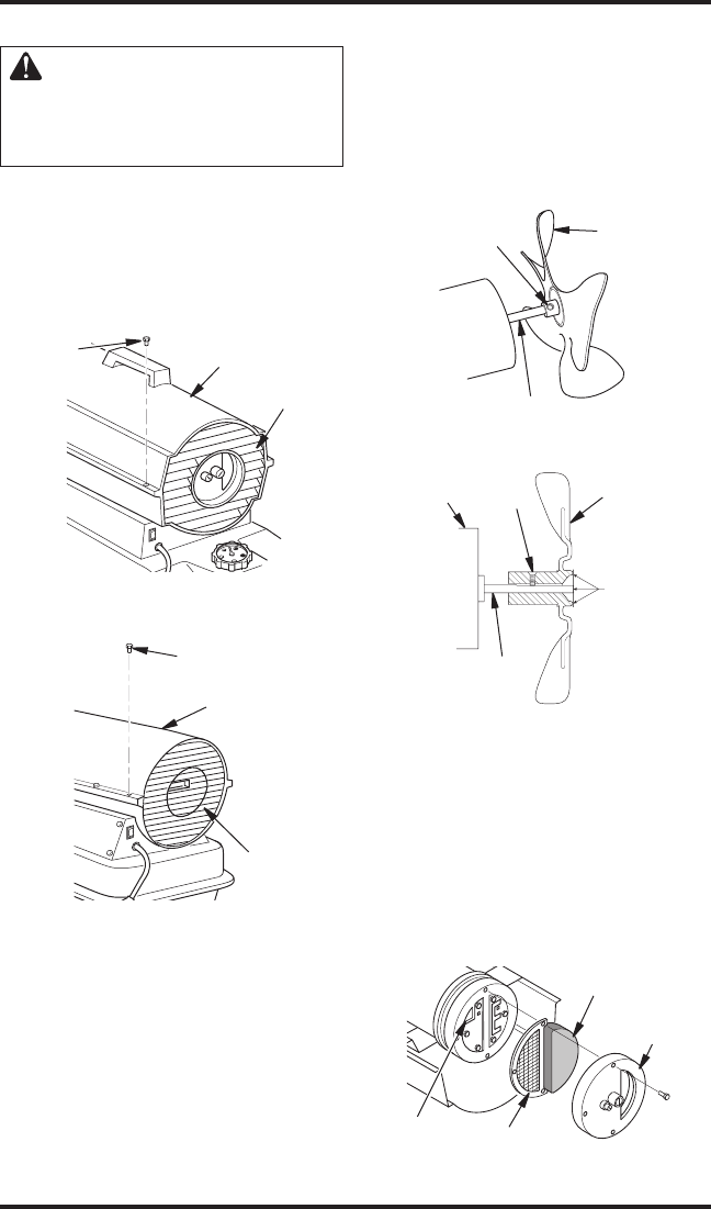
UPPER SHELL REMOVAL
1. Remove screws along each side of heater using
5/16" nut-driver. These screws attach upper and
lower shells together. See Figure 11 or 12.
2. Lift upper shell off.
3. Remove fan guard.
Upper Shell
Fan Guard
Figure 11 - Upper Shell Removal,
40/55/70 Models Only
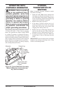
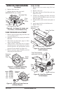
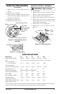
Figure 12 - Upper Shell Removal,
115/165 Models Only
Fan Guard
Upper Shell
Screw
Screw
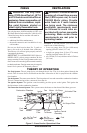
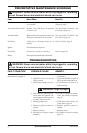
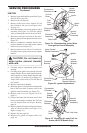
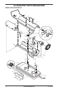
FAN
IMPORTANT: Remove fan from motor shaft
before removing motor from heater. The weight
of the motor resting on the fan could damage the
fan pitch (see Figure 13).
1. Remove upper shell (see Figure 11 or 12).
2. Use 1/8" allen wrench to loosen setscrew
which holds fan to motor shaft.
3. Slip fan off motor shaft.
Motor Shaft
Setscrew
Figure 13 - Fan, Motor Shaft, and
Setscrew Location
Motor
Shaft
Fan
Setscrew
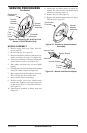
Figure 14 - Fan Cross Section
Fan
Flush
Motor
4. Clean fan using a soft cloth moistened with
kerosene or solvent.
5. Dry fan thoroughly.
6. Replace fan on motor shaft. Place fan hub flush
with end of motor shaft (see Figure 14).
7. Place setscrew on flat of shaft. Tighten setscrew
firmly (40-50 inch-pounds/4.5-5.6 n-m).
8. Replace fan guard and upper shell.
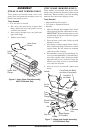
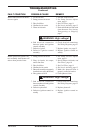
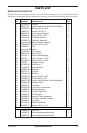
AIR OUTPUT, AIR INTAKE AND LINT
FILTERS
1. Remove upper shell (see Figure 11 or 12).
2.
Remove filter end cover screws using 5/16" nut-
driver (see Figure 15 or Figure 16, page 11).
3. Remove filter end cover.
4. Replace air output and lint filters.
5. Wash or replace air intake filter (see Preventa
-
tive Maintenance Schedule, page 8).
Air Intake Filter
Lint Filter
Filter End
Cover
Air Output Filter
Figure 15 - Air Output, Air Intake, and
Lint Filters, 40/55/70 Models Only