


www.desatech.com
116699-01B
8
SPECIFICATIONS
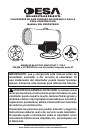
• Output Rating - 225,000 to 375,000 (Btu/Hr)
• Fuel - Propane/LP Vapor Only
• Fuel Consumption
Gallons(liters)/Hour - 2.5 (9,4) Min/4.0 (15) Max
Pounds(kg)/Hour - 10.4 (4.7) Min/17.4 (7.9) Max
• Supply Pressure To Regulator
Minimum* - 25 psig (172 kPa)
Maximum - Tank Pressure
• Regulator Outlet Pressure -
7-20 psig (48 to 138 kPa)
• Hot Air Output - 1500 CFM (
pi³/min)
• Motor - 1725 RPM, 1/5 HP
• Electric Input - 120 V/60 Hz
• Amperage - 4.2
• Ignition - Electronic Direct Spark, D.S.I.
* (for purposes of input adjustment)
ACCESSORIES
Purchase accessories and parts from your nearest
dealer or service center. If your dealer or service
center can not supply an accessory or part, either
contact your nearest Parts Central (listed in the
separate Authorized Service Center booklet) or
call DESA Heating Products at 1-866-672-6040
for referral information. You can also write to the
address listed on the back page of this manual.
Fuel Gas Connector: LPA4020
A POL adapter with excess-flow check valve.
Thermostat: HA1210
TECHNICAL SERVICE
You may have further questions about installation,
operation or troubleshooting. If so, contact DESA
Heating Productsʼ Technical Service Department
at 1-866-672-6040. When calling please have your
model and serial numbers of your heater ready.
You can also visit DESA Heating Productsʼ techni
-
cal services web site at www.desatech.com.
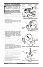
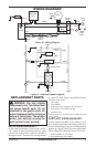
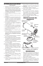
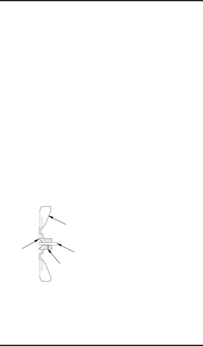
15. Replace fan on motor shaft. Make sure set
-
screw is touching back of flat surface on motor
shaft (see Figure 9).
16. Place setscrew on flat of shaft. Tighten set
-
screw firmly (40-50 inch-pounds).
17. Remove two nuts and bolts securing motor
mount to shell.
18. Pull motor and fan from shell. Turn motor
and fan around. Carefully place back in shell.
Note: Fan will go into shell first.
19. Line up mounting holes in shell with holes on
motor mount. Replace four bolts through shell
and motor mount. Insert bolts from outside of
heater. Tighten nuts firmly.
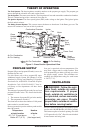
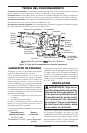
20. Route motor wires through hole in bottom of
shell (see Figure 6, page 7).
21. Connect motor wires as follows (see Figure
5, page 7):
• white wire—to terminal board
Note: Attach to empty connector on white
wire side of terminal board
• black wire—to terminal board
Note: Attach to empty connector on black
wire side of terminal board
• blue wire—to thermal switch wire
• orange wire—to solenoid valve
• green wire—to grounding screw on shell
22. Replace side cover.
23. Replace fan guard.
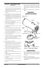
Fan
Hub
Setscrew
Motor
Shaft
Figure 9 - Fan Cross Section
SERVICE PROCEDURES
Continued
SERVICE PUBLICATIONS
You can receive an Illustrated Parts List free of
charge. Send your request and a self-addressed,
stamped envelope to DESA Heating Products
(address on back page). Be sure to include the
heater model number. You can purchase a service
manual for $5. Make check payable to DESA
Heating Products.