


8
104001
PORTABLE FORCED AIR HEATER
MODEL BY150ECB 150,000 Btu/Hr
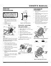
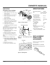
FUEL FILTER
1. Remove side cover screws using
5/16" nut-driver.
2. Remove side cover.
3. Pull upper fuel line off fuel filter
neck.
4. Carefully pry bushing, fuel filter,
and lower fuel line out of fuel tank.
5. Wash fuel filter with clean fuel and
replace in tank.
6. Attach upper fuel line to fuel filter
neck.
7. Replace side cover.
Figure 10 - Fuel Filter Removal
Side
Cover
Fuel Filter,
Bushing, and
Lower Fuel
Line
Upper
Fuel
Line
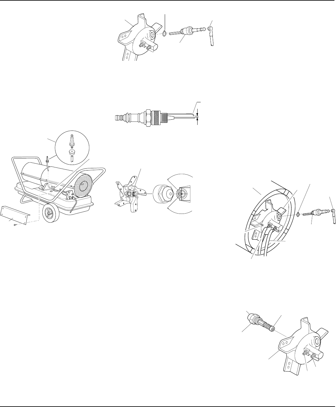
SPARK PLUG
1. Remove upper shell (see page 7).
2. Remove fan (see page 7).
3. Remove spark plug wire from spark
plug.
4. Remove spark plug and wave spring
washer from burner head using 13/16"
open-end wrench.
5. Clean and regap spark plug electrodes
to .110" (2.8 mm) gap.
6. Install spark plug and wave spring
washer in burner head. Torque 40 to
60 inch-pounds. Adjust (if necessary)
to bring side electrode into the accept-
able range (see figure 13).
7. Attach spark plug wire to spark plug.
8. Replace fan (see page 7).
9. Replace fan guard and upper shell.
Figure 11 - Spark Plug Removal
Figure 12 - Spark Plug Gap
Spark Plug Wire
Spark
Plug
Burner
Head
.110” Gap
(2.8 mm)
Bend
Here to
Adjust
Gap
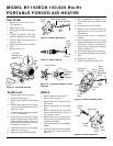
NOZZLE
1. Remove upper shell (see page 7).
2. Remove fan (see page 7).
3. Remove fuel and air line hoses from
burner head.
4. Remove spark plug wire from spark
plug.
5. Remove spark plug and wave spring
washer from burner head using 13/
16" open-end wrench.
6. Remove three screws using 5/16" nut-
driver and remove burner head from
combustion chamber.
7. Place burner head into vise and lightly
tighten.
8. Carefully remove nozzle from burner
head using 5/8" socket wrench (see
Figure 15).
9. Blow compressed air through face of
nozzle. This will free any dirt in nozzle
area.
10. Inspect nozzle seal for damage.
11. Replace nozzle into burner head and
tighten firmly (9.1-12.4 n-m /80-110
inch-pounds).
12. Attach burner head to combustion
chamber.
13. Install spark plug and wave spring
washer in burner head. Torque 40 to 60
inch-pounds. Adjust (if necessary) to
bring side electrode into the acceptable
range (see figure 14).
14. Attach spark plug wire to spark plug.
15. Attach fuel and airline hoses to burner
head.
16. Replace fan (see page 7).
17. Replace fan guard and upper shell.
270˚
ACCEPTABLE RANGE
FOR SIDE ELECTRODE
Side Electrode
270°
Acceptable
Range for
Side
Electrode
Figure 13 - Acceptable Range For Side
Electrode
Wave Spring Washer
Figure 14 - Removing Burner Head
Figure 15 - Removing Nozzle
Air Line
Hose
Screw
Combustion
Chamber
Burner
Head
Spark Plug
Wire
Spark
Plug
Fuel Line
Hose
Nozzle
Face
Nozzle Seal
Nozzle
Burner
Head
Fuel
Line
Fitting
Air
Line
Fitting
Wave
Spring
Washer