


PC-BDV37N (02267) Conversion Kit
2
105822
Screw
Glass Door
Assembly
Lower Bracket for
Glass Door Assembly
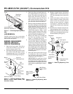
Figure 2 - Removing/Replacing Glass
Door
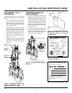
LOG REMOVAL
Carefully remove the log set and ember
material from around the burner and place
them outside the fireplace.
BURNER, MAIN BURNER
ORIFICE, AND PILOT
ORIFICE CONVERSION
1. Open lower louver panel. This allows
access below firebox to gas line con-
nections and gas control valve.
2. Disconnect flare fitting connected to the
brass elbow inside the bottom control
compartment area. Use a 3/4" open end
wrench on the flare fitting (see Figure 3).
3. Turn brass elbow and main burner ori-
fice counterclockwise to remove from
burner. The orifice is threaded into the
burner inlet. The elbow may have a
slight resistance since the orifice has
been sealed with RTV silicone. Use a
7/8" open end wrench or channel lock
pliers for elbow and orifice removal.
4. Remove existing main burner orifice from
brass elbow and replace with main burner
orifice supplied with conversion kit.
Note:
The new main burner orifice will
have the number 132 stamped on it for
identification purposes. Apply a small
amount of thread sealant to the orifice
before tightening (see Figure 4). Sealant
must be resistant to Propane/LP gas.
5. Remove the burner by loosening the
two 5/16" hex mounting screws (see
Figure 3). Lift burner up and out.
6. Convert the pilot burner by changing out
the pilot orifice. Remove the compres-
sion nut and compression sleeve from
the pilot. Remove the pilot orifice from
inside the pilot barrel (see Figure 5). Re-
place with the pilot orifice supplied with
this kit.
Note:
The new pilot orifice has
the number 30 stamped on it for identi-
fication purposes.
7. Place open end of pilot orifice on top
of compression sleeve and carefully
slide up inside pilot burner. Tighten
compression nut (see Figure 5).
IMPORTANT:
Be careful not to bend
or kink aluminum tubing during conver-
sion. Make sure the compression sleeve
and pilot orifice are properly mated and
aligned before retightening the compres-
sion nut.
Fireplace
Floor
Burner
Main Burner
Orifice
RTV
Silicone
Brass Elbow
Flare Fitting
Aluminum Tubing
Figure 3 - Removing/Replacing Main
Burner Orifice, Brass Elbow, and
Aluminum Tubing
Main Burner
Orifice (18mm
Hex)
Brass Elbow
Apply Thread
Sealant Here
Only
Figure 4 - Removing/Replacing Main
Burner Orifice
8. Replace original burner with burner
supplied with kit. Attach with the two
5/16" hex mounting screws removed in
step 5.
9. Attach main burner orifice and brass
elbow assembly to burner. Place main
burner orifice into threaded end of
burner and turn clockwise to tighten
(see Figure 3). Align the brass elbow
with the flare fitting on the aluminum
tubing.
10. Reconnect the aluminum tube flare fit-
ting onto the brass elbow (see Figure 3).
11. Reapply RTV silicone to seal area where
orifice passes through the bottom com-
bustion chamber (see Figure 3).
Thermopile
Pilot Burner
Thermocouple
Piezo Ignitor
12mm
Hex
Pilot Orifice
Compression
Sleeve
Compression Nut
(10mm Hex)
Figure 5 - Removing/Replacing Pilot
Orifice
5/16" hex
Mounting Screw