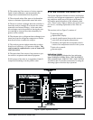
® The coalescing filter removes oil mists, separates
liquid oil and condensate, and automatically dis
-
charges these contaminants from the purifier.
¯ The activated carbon filter removes hydrocarbon
vapors to eliminate objectionable tastes and odors.
° The air-to-air heat exchanger heats the air before it
enters the catalyst cartridge ² to increase the carbon
monoxide conversion efficiency. At the same time,
this exchanger cools the purified air leaving the cata
-
lyst cartridge to increase the relative humidity for
greater worker comfort.
± The reheater (air-to-refrigerant heat exchanger) uses
waste heat from the refrigerant compressor to further
heat the air before it reaches the catalyst.
² The catalyst converts carbon monoxide to carbon
dioxide at an efficiency of 95 percent or higher. The
catalyst must be replaced once a year to assure effi
-
cient conversion.
³ The particulate filter removes fine particles to pro-
tect sensitive respirators and related equipment.
´ 100 percent of the inlet air is supplied as Grade D
compressed breathing air at the purifier outlet.
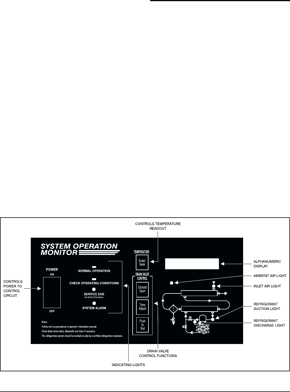
SYSTEM OPERATION MONITOR
The System Operation Monitor measures and displays
critical air and refrigerant temperatures, signals operat
-
ing conditions which may affect dryer performance,
and enables panel adjustment of the automatic drain
valve. There is also a light to indicate the need for rou
-
tine service, including replacement of the filter ele
-
ment.
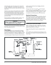
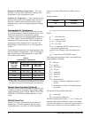
The monitor (refer to Figure 2) consists of:
•
indicating lights
•
alphanumeric display
•
controls (push buttons) that provide access to
critical air and refrigerant temperatures
•
schematic with lights that correspond to the lo
-
cations of the temperature sensors in the system
•
drain valve controls
•
thermocouples
Indicating Lights
The System Operation Monitor has four indicating
lights: NORMAL OPERATION, CHECK OPERAT-
ING CONDITIONS, SERVICE DUE AND SYSTEM
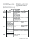
ALARM. Table IV provides instructions for using the
indicating lights to monitor dryer operation.
Pyramid 8000
®
Series Purifiers (Bulletin 289) 5
Figure 2. System Operation Monitor


