Clearance
Allow adequate clearance on all four sides of the puri
-
fier for cooling air flow and for service and mainte
-
nance access. Above the purifier, allow at least
one-half the height of Model 8DM25, 8DM50 or
8DM75 to replace cartridges. Above Model 8DM100
or 8DM150, allow the full height of the purifier. See
Table II for purifier dimensions.
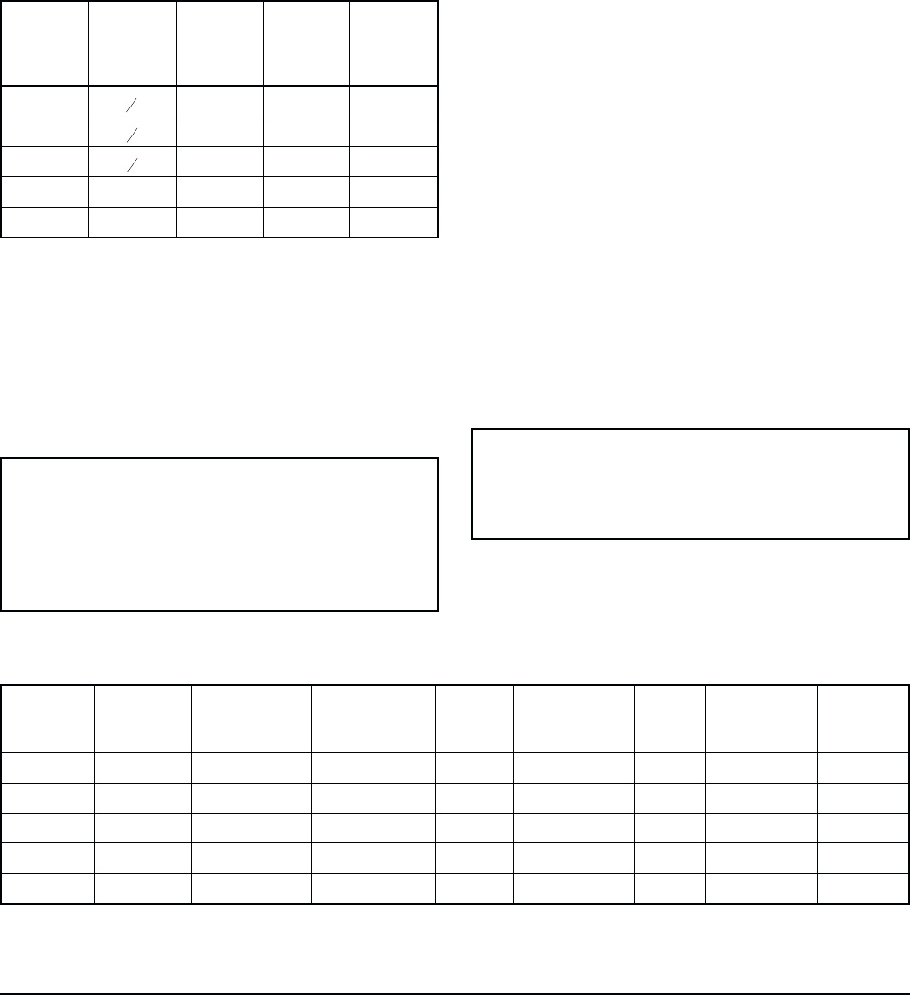
Table II
Purifier Dimensions*
Model
Inlet/
Outlet
Conn.
(in FPT)
Height Width Depth
8DM25
1
2
45 24 24
8DM50
3
4
45 30 30
8DM75
3
4
45 30 30
8DM100 1 55 36 36
8DM150 1 55 36 36
* All dimensions are in inches.
Ambient Air Temperature
Purifier ambient air temperature must be between 50°F
and 100°F. Higher temperatures (up to 120°F) can be
tolerated if inlet air flow is decreased (see Airflow sec-
tion). Operation outside the recommended ambient
temperature range will cause poor purifier perform-
ance.
DANGER
Never operate thepurifier in atmospheres be
-
low 50°F or above 120°F. Operation outside
this range will cause poor purifier perform
-
ance and may result in illness, injury or
death.
Location
Locate the purifier under cover in a clean, dry, well-
ventilated area. Install the purifier on a level base. Pro
-
tect the purifier from heavy vehicles or other moving
equipment likely to cause damage. Bolt the purifier to
the foundation if the installation area is subject to vi
-
brations. A bolt hole is located in each leg.
Air Compressor Equipment
Air compressor equipment must be located and main
-
tained to prevent the entry of oxygen-deficient air or
grossly contaminated air into the purifier . Do not op
-
erate lubricated compressors at temperatures high
enough to cause chemical breakdown of the lubricant.
Breakdown temperatures vary; contact the lubricant
manufacturer for details.
Install the purifier downstream of an aftercooler and
separator (with functioning drain valve) so that purifier
inlet air is between 40°F and 100°F and contains no
liquid water.
Air Piping and Connections
The customer must furnish all external piping. Piping
must be rated for the maximum operating pressure and
temperature given on the purifier data plate and must
conform to applicable codes. Support all piping. Do
not allow the weight of the piping to stress the purifier
connections.
DANGER
Do not hydrostatically test the piping with the
purifier installed in the air system. Water will
damage the catalyst.
Connect the compressed air supply to the purifier inlet.
Connect the breathing air distribution line to the puri
-
fier outlet. (See Table III for connection sizes.) Inlet
Pyramid 8000
®
Series Purifiers (Bulletin 289) 3
Table III
Purifier Specifications
Model
Rated*
Capacity
(scfm)
Inlet/Outlet
Connections
(inches FPT)
Electrical
Service
(V/Ø/Hz)
Running
Load
Amps
Refrigerant
Compressor
Power (hp)
Fan
Power
(Watts)
Refrigerant
Charge
(Type R-22)
Heat
Rejection
(BTUH)
8DM25 25 ½ 115/1/60 5.0 ¼ 5 2 lb 2,780
8DM50 50 ¾ 115/1/60 10.0 ½ 9 3 lb 6,000
8DM75 75 ¾ 208-230/1/60 7.0 ¾ 50 4 lb 6 oz 9,890
8DM100 100 1 208-230/1/60 7.0 1 50 5 lb 8 oz 11,060
8DM150 150 1 208-230/1/60 10.0 1½ 50 8 lb 8 oz 14,300
*Ratingconditionsare100°Finletairtemperature,100psiginlet airpressure,100%inletrelativehumidityand100°Fambienttemperature.If oper
-
ating conditions are different from rating conditions, consult Deltech for purifier capacity.


