


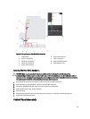
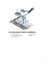
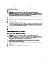
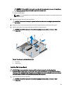
5. screw (bottom) 6. VGA module
Installing The VGA Module
NOTE: This procedure applies only to the 8-hard drive system.
CAUTION: Many repairs may only be done by a certified service technician. You should only perform
troubleshooting and simple repairs as authorized in your product documentation, or as directed by the online or
telephone service and support team. Damage due to servicing that is not authorized by Dell is not covered by your
warranty. Read and follow the safety instructions that came with the product.
1. Push the VGA module into the chassis and align the threaded screw hole on the VGA module with the screw hole
on the chassis.
2. Using a #2 Philips screwdriver, replace the screw (at the bottom of the chassis) that secures the VGA module to the
chassis.
3. Replace the control panel.
4. Connect the VGA module cable to the VGA module.
CAUTION: The display module connector is a ZIF (zero insertion force) connector. Ensure that the locking tab
on the connector is released before removal and insertion. The locking tab must be engaged after insertion.
5. Connect the display module cables to the control panel board.
6. Close the system.
7. If applicable, install the front bezel.
8. Reconnect the system to its electrical outlet and turn the system on, including any attached peripherals.
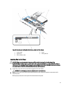
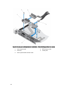
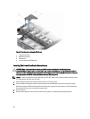
Power Distribution Board Shroud
Removing The Power Distribution Board Shroud
CAUTION: Many repairs may only be done by a certified service technician. You should only perform
troubleshooting and simple repairs as authorized in your product documentation, or as directed by the online or
telephone service and support team. Damage due to servicing that is not authorized by Dell is not covered by your
warranty. Read and follow the safety instructions that came with the product.
CAUTION: Never operate your system without the power distribution board shroud. The system may get
overheated, which may result in loss of performance.
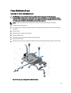
1. Turn off the system, including any attached peripherals, and disconnect the system from the electrical outlet and
peripherals.
2. Open the system.
3. Lift the power distribution board (PDB) shroud away from the system.
97