48 Getting Started Guide
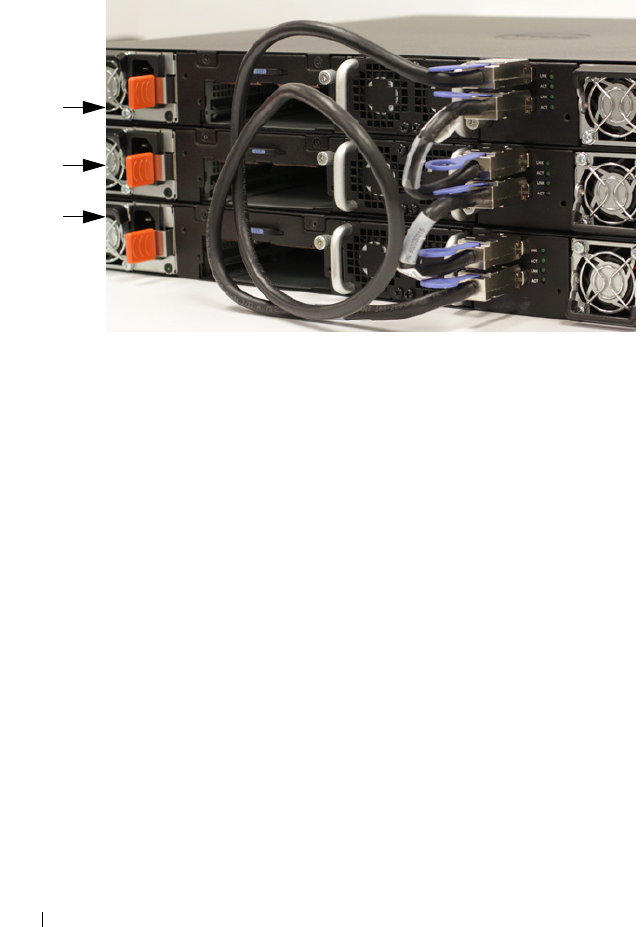
Figure 1-23. Connecting a Stack of Switches
The stack in Figure 1-23 is connected in a ring topology and has the following
physical connections between the switches:
• The bottom mini-SAS port on Unit 1 is connected to the top mini-SAS
port on Unit 2.
• The bottom mini-SAS port on Unit 2 is connected to the top mini-SAS
port on Unit 3.
• The bottom mini-SAS port on Unit 3 is connected to the top mini-SAS
port on Unit 1.
Stacking Standby
The stacking feature supports a Standby or backup unit that assumes the
Master unit role if the Master unit in the stack fails. As soon as a Master
failure is detected in the stack, the Standby unit initializes the control plane
and enables all other stack units with the current configuration. The Standby
unit maintains a synchronized copy of the running configuration for the
stack. The Standby unit is automatically selected in the stack; however, you
can use the CLI to select a different stack member as Standby. See the User’s
Configuration Guide or the CLI Reference Guide for more information.
Unit 1
Unit 2
Unit 3


