


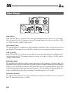
INST Switch
This switch selects the 1/4Ó Instrument input as the source for the compressor.
DRIVE control
This control sets the amount of gain that will be applied at the input of the vacuum tube stage present
in the Compressor section. This control offers tube drive control (with its sonic stamp) to any signal
routed through the Compressor.
SC (SIDECHAIN) ENABLE switch
This switch enables the Sidechain processing loop. The Sidechain in and out connectors on the 566
rear panel allow external processing of the CompressorÕs detector signal. This switch has no effect if
there is nothing plugged into the Sidechain loop even though the switch will light when pressed. For
more discussion of the Sidechain see page 16.
SC (SIDECHAIN) MON switch
This switch allows you to monitor the sound of the Sidechain processing. The switch will light when
pressed to indicate that you are listening to the Sidechain; not the main signal path.
CONTOUR switch
This switch adds a gentle low frequency de-emphasis into the detector path (this is identical to hav-
ing an equalizer in the Sidechain loop, only weÕve done it for you). This is extremely useful in keep-
ing low frequency program material from ÒmufflingÓ or Òpunching holes inÓ the compressed signal.
This feature allows faster attack times and higher compression ratios with less artifacts. The switch
will light indicating contouring is activated.
BYPASS switch
This switch bypasses the compression section completely. The input is ÒhardwiredÓ to the output
bypassing the tube amplification and VCA circuitry. This feature is very useful for setting optimum
compression and gain settings because it gives you an instant reference to the amount of effect youÕve
introduced to your signal.
LEVEL control
This is the output gain control (also known as a Ògain compensationÓ or Òmakeup gainÓ control). It
is used to compensate for signal level lost due to compression and for excess gain contributed by the
tube drive section. There is +/- 15 dB of gain control available with this knob.
PeakPlusª Limiter THRESHOLD control
This control sets the threshold level at which the PeakPlus
ª
Limiter circuit becomes active. The
threshold range is from 0 dBu to +22 dBu (off). The PeakPlus
ª
Limiter stage is a unique program
Limiter featuring Intelligent Predictive Limiting
ª
. Its function is to monitor the input signal and
intelligently predict the amount of gain reduction needed to keep the output signal below the ceiling
set by the PeakPlus
ª
control.
7