


Note that since the PeakPlus
ª
Limiter is a fail-safe Limiter it must come after the Output Gain con-
trol. If the Output Gain is set too high as compared to the PeakPlus
ª
Level control, continuous lim-
iting can occur. While PeakPlus
ª
is typically used as a protective function, creative effects can be
achieved by intentionally driving the signal into heavy PeakPlus
ª
limiting.
Great care has gone into the design of the PeakPlus
ª
Limiter to keep it acoustically transparent.
Appropriate use of it can protect your gear while keeping the signal free of artifacts. Peak Plus
ª
also
serves to prevent digital overload when used in conjunction with the dbx Type IV
ª
Conversion
System option.
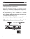
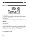
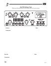
DRIVE LEVEL switch
This configures the meter to show the signal level at the input to the vacuum tube. Note that high gain
settings can result in excessive movement of the meter as the needle contacts the endpin. In this sit-
uation itÕs best to briefly check the drive level and then switch to one of the other meter modes.
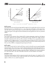
GAIN REDUCTION switch
This configures the meter to show the amount of gain reduction due to compression. The lower mark-
ings on the meter show increasing gain reduction from right (0 dB) to left (-30dB). Note that when
configured to the Gain Reduction setting, the meter swings from the fully right position and not the
0 dB position indicated on the top line of the meter.
OUTPUT LEVEL switch
This configures the meter to show the output signal level. This works in conjunction with the output
level assignment switch on the back of the 566. When the rear switch is set to +4 dBu, a meter read-
ing of 0 VU corresponds to +4 dBu output. When the rear switch is set to -10 dBV, a meter reading
of 0 VU corresponds to -10 dBV output.
LINK Switch:
This switch changes the 566 from two independent compressors into a stereo compressor, and also
links the two independent limiters into a stereo limiter. In stereo link mode a peak in either side of
the compressor will activate both compressor channels equally. This helps to preserve stereo imag-
ing. Channel One is the master and Channel Two is the slave except for the following controls:
Sidechain Enable, Sidechain Monitor, Contour, and Bypass switches. Additionally, Channel Two's
Compressor Threshold LEDs and
PeakPlusª Limiter
LED will be disabled, while both channels'
Gain Reduction metering will identically indicate the amount of gain reduction occurring. It is
important to note that while Channel One is the master as far as the controls go, both channels have
equal precedence as far as signal processing is concerned. The dbx 566 uses True RMS Power
Summing
ª
, an extremely accurate and musical way to combine detector outputs in a stereo situa-
tion. The Link Switch will light to indicate that the 566 is in the stereo link mode.
8