


Dayton Installation, Operation, Maintenance and Parts Manual
Dayton High Intensity Heaters
®
3E132 thru 3E134, 3E460 thru 3E462,
5VD57 thru 5VD66, 3VH34 thru 3VH37
E
N
G
L
I
S
H
22
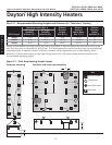
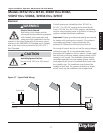
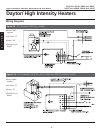
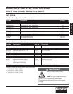
Heater Assembly Components
NOTE: Replacement burners are called “rayheads”
with rod inserts (part no. DR-RH and DR-ROD).
Path of exhaust
Electrode Assembly
Rods
Gas Orifice
Manifold End
Frame Assembly
Side Frame
Manifold Pressure Tap
Rayhead Assembly
with Ceramics
Heat Shield
Figure 4.1 - Heater Assembly Components (side view)
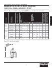
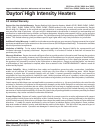
Figure 4.2 - Spark Electrode Side View
Side Frame
Ceramic
Tile
Rods
Set gap to 1/8”
Electrode Bracket
Proper installation results
in 1/16” clearance from
face of ceramic
Electrode
Brass Union
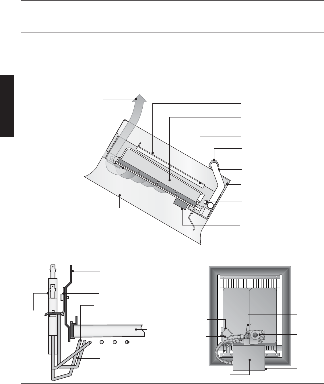
Reflector Shield
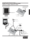
Figure 4.3 - Heater Components (rear view)
Ceramic grids are not sold separately, order full
assembly (part no. DR-RH).
Cross-over
Bracket
High Voltage
Wire
Low Voltage
Wire
Circuit Board
Gas Valve
Junction
Box