


Dayton Installation, Operation, Maintenance and Parts Manual
Dayton High Intensity Heaters
®
3E132 thru 3E134, 3E460 thru 3E462,
5VD57 thru 5VD66, 3VH34 thru 3VH37
E
N
G
L
I
S
H
Ventilation
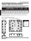
It is required that the upper levels of the space to be
heated are properly ventilated to supply combustion
air to the heaters and to sufficiently dilute the products
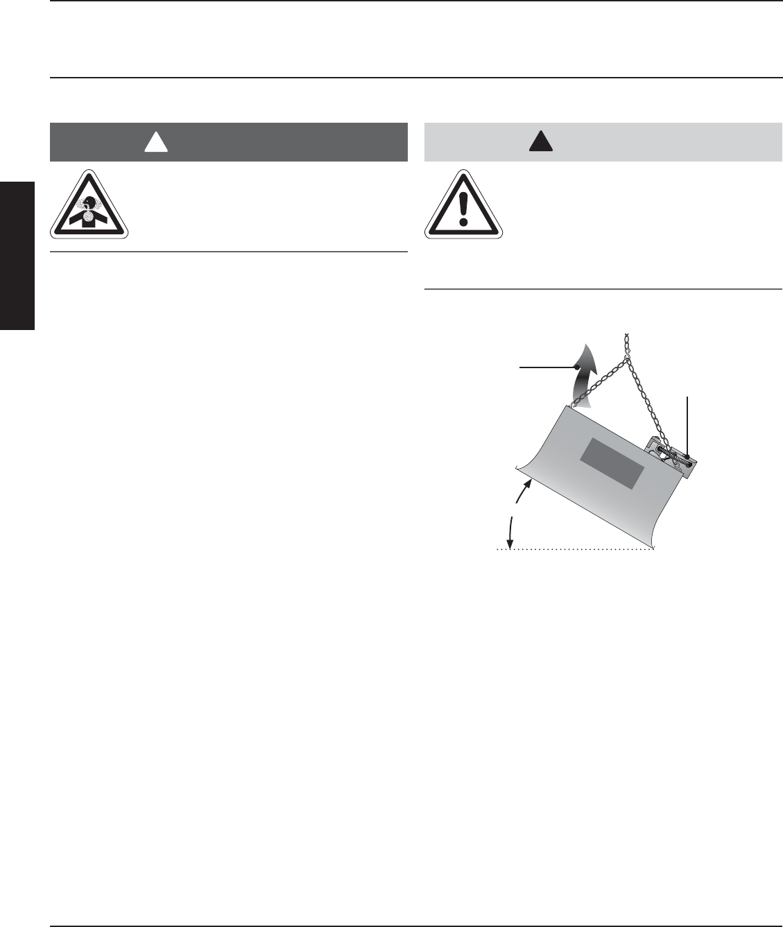
of combustion. It is also required that the flue discharge
area is kept clear of gas piping and electrical wiring (see
Figure 2.6).
This infra-red heater must be vented in accordance with
national, state, provincial and local codes and the
guidelines in this manual. In the United Sates refer to
the latest edition of ANSI Z223.1 (NFPA 54) and in
Canada refer to the latest edition of the CAN/CGA
B149.2 Standard.
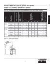
Provisions must also be made to provide sufficient fresh
air intake area and exhaust air outlet area. For proper
ventilation, a positive air displacement of 4.0 CFM per
1000 BTU/H of natural gas consumed must be
provided. If propane is used, a positive air displacement
of 4.5 CFM per 1000 BTU/H of propane gas
consumed must be provided.
Where insufficient air movement exists, induced air
displacement is required. A balanced system is essential
to avoid negative building pressure which causes
excessive infiltration, unfavorable drafts and affects
combustion efficiency.
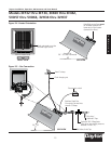
Air displacement may be accomplished by either gravity
or mechanical means. Mechanical exhausters are
preferred and typically mounted at high points on the
roof where stagnant air accumulates inside the building.
For a flat roof, considerations of prevailing winds, high
and low pressure areas, and distribution of air
movement must be taken into consideration when
locating exhausters.
14
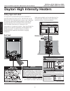
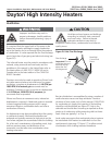
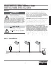
Figure 2.6 Hot Flue Discharge
Best air distribution is accomplished by using a number of
small exhausters versus one large exhauster. Provide a
minimum of one square inch of inlet area per 1000 BTU/H
for combustion air supply. Inlet opening in the building
should be well distributed (see Figure 2.1) high in the
sidewalls and should direct incoming air upward to dilute
products of combustion while preventing drafts at lower
levels. Inlets are typically 1 to 3 sq. ft.
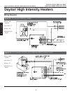
Local codes may require that mechanical exhaust systems
be interlocked with heaters to enable both to function
simultaneously (see page 17, Figure 2.7) or allow control
of exhausters with a ceiling mounted humidistat.
Da
yton
Important! Do not
install gas piping or
electrical wiring
above the flue
discharge area!
Manifold/
Control End
Down
Flue discharge
SIDE VIEW
20˚ - 35˚
WARNING
!
!
Improper ventilaton may result in
property damamge, health problems,
carbon monoxide poisoning, injury or
death.
Ventilate enclosed spaces and buildings
according to national, state, provincial
and local codes. Failure to provide
adequate ventilation may result in
equipment malfunctions, condensation and other air
quality issues.
CAUTION
!