


Da
yton
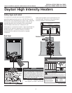
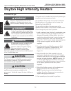
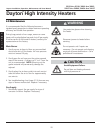
Steel C-clamp
Chain hanging set
Drip Leg/
Sediment Trap
Optional 325-3 Regulator
(Use when gas supply pressure
exceeds 14: W.C.P.)
Ball Valve / Inlet Tap
Disconnect switch
Stainless Steel Gas
Connector, formed into
smooth C-Shape
®
Dayton Installation, Operation, Maintenance and Parts Manual
Models 3E132 thru 3E134, 3E460 thru 3E462,
5VD57 thru 5VD66, 3VH34 thru 3VH37
E
N
G
L
I
S
H
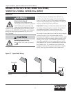
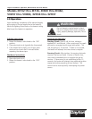
Angled at
20˚ - 35˚ from horizontal
Da
yton
13
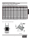
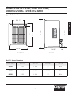
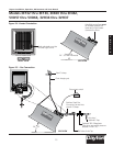
Figure 2.4 Heater Orientation
Figure 2.5 • Gas Connection
Manifold control box must
be located towards the
lower end of the heater
(towards the floor).
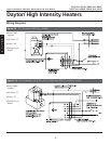
Mount Heater Level
Spark electrode must be
in lower right corner.
FRONT VIEW
TOP VIEW
SIDE VIEW
20˚ - 35˚
SIDE VIEW