


Version B - For Reduction G016.J
®
Dayton Operating Instructions and Parts Manual
9
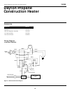
Model 3VG80
5. Place setscrew on flat of shaft. Tighten
setscrew firmly (40-50 inch-pounds).
6. Place motor, motor mount, and fan
guard into rear of heater shell (See
Motor, page 8, steps 14 through 18).
Maintenance (Continued)
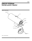
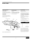
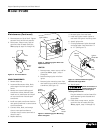
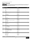
Fan
Hub
Setscrew
Motor
Shaft
Figure 10 - Fan Cross Section
SPARK TRANSFORMER
1. Remove base tray.
2. Locate and disconnect white, black,
and orange wires from spark trans-
former.
3. Remove two screws holding spark
transformer to base. Remove sheet
metal nuts on transformer and install
on new transformer. Discard spark
transformer.
4. Install new spark transformer. Position
new spark transformer in same manner
as old transformer.
5. Connect white, black, and orange
wires to new spark transformer.
Connect wires to correct terminals as
noted in step 2.
6. Replace base tray.
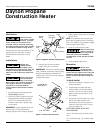
Bushing
Ignitor Wire
Figure 11 - Removing Ignitor Wire from
Spark Transformer
IGNITOR
1. Remove motor, motor mount, and fan
guard (See Motor, page 7, steps 1
through 6).
2. Remove orange ignitor wire from
ignitor.
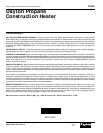
3. Remove ignitor mounting screw from
rear head using nut-driver or standard
screwdriver (See Figure 12).
4. Remove ignitor from rear head.
5. Install new ignitor. Attach ignitor to
rear head with ignitor mounting screw.
6. Attach ignitor wire.
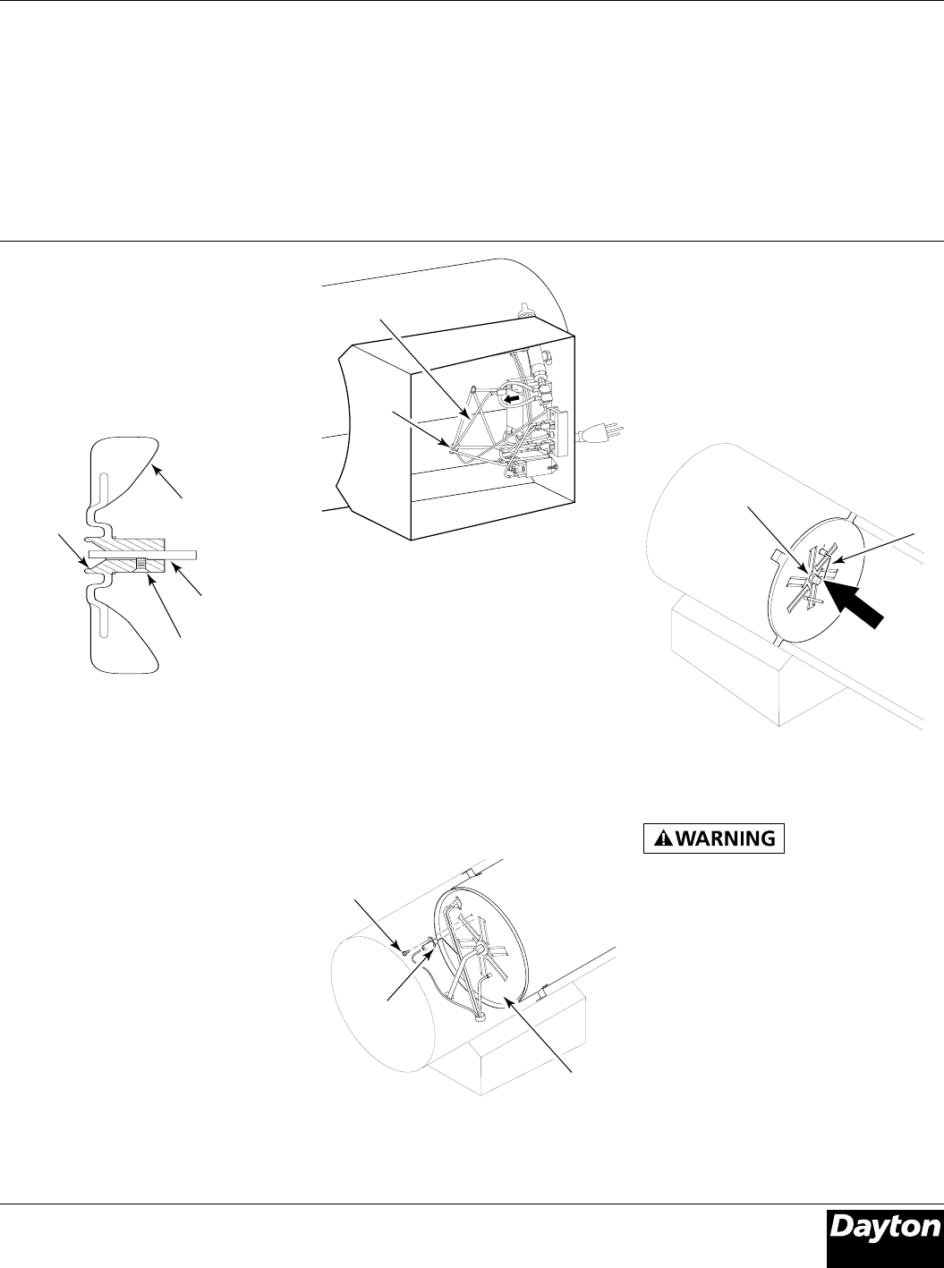
7. Check gap between ignitor electrode
and target plate. Gap should be .13"
to .15" (See Figure 13).
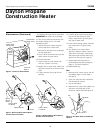
Figure 12 - Removing Ignitor Mounting
Screw and Ignitor
Rear
Head
Ignitor
Figure 13 - Clearance between Ignitor
Electrode and Target Plate
Burner
Nozzle
Gap
Area
Ignitor
Electrode
8. Test for spark.
Make sure heater is
disconnected from
propane supply. Heater could ignite
causing severe burns.
Plug into extension cord and watch for
spark between ignitor electrode and
target plate.
9. Place motor, motor mount, and fan
guard into rear of heater shell (See
Motor, page 8, steps 14 through 18).
Ignitor
Mounting
Screw