


Version B - For Reduction G016.J
®
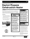
Dayton Operating Instructions and Parts Manual
13
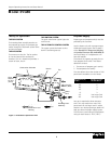
Model 3VG80
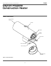
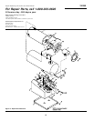
Repair Parts List
( ) Not shown. (*) Standard hardware item, available locally.
1 Base Tray 102362-01 1
2 *Hex TPG Screw, 10-16 X 38 M11084-26 15
3 Base 103917-01AA 1
4 Nozzle 099138-02 1
5 Shell Kit 098511-216 1
6 *Hex TPG Screw,10-16 X .75 M11084-29 2
7 Handle M51104-01 1
8 Combustion Chamber Kit 098512-61 1
9 Thermocouple 099538-01 1
10 Thermocouple Clip 099237-01 1
11 Fuel Tube Kit 099334-02 1
12 Fan M51153-01 1
13 Motor 102366-01 1
14 Motor Bracket 102380-01 1
15 Hex Lock Nut, 1/4-20 NTC-4C 2
16 Fan Guard 102315-02 1
17 Control Knob 099393-03 1
18 Thermal Switch Kit (Including Wire Assemblies) 101732-04 1
19 lgnitor Electrode 102487-01 1
20 lgnitor Cable 097806-02 1
21 *Screw, Hex TPG, 8-18 X .38 M11084-38 2
22 Power Cord 098219-17 1
23 Strain Relief Bushing M11143-1 1
24 Valve Kit 103846-01 1
25 Ignition Control 102601-01 1
26 Wire Assembly (Relay) 079010-30 1
27 Wire Assembly (Relay) 079010-19 1
28 Wire Assembly (Relay) 097951-14 1
29 Relay Kit 103847-01 1
30 U-Clip Nut, #6 X .12 102602-01 2
31 Wire Assembly (lgnition Control) M9900-170 1
32 Wire Assembly (lgnition Control) M16841-56 1
33 Wire Assembly (lgnition Control) M16841-68 1
34 Terminal Board 099125-11 1
35 Break Mandrel Rivet, 3/16 099157-01 1
Service Center List M50985-01 1
Tradename Decal 099153-05 1
Operation Decal 105350-02 1
Warning Decal 105351-01 1
Electrical Decal 102599-01 1
Reference
Number Description Part No. Quantity
Use only original replacement parts. This heater must use design-specific parts. Do not substitute or use
generic parts. Improper replacement parts could cause serious or fatal injuries. This will also protect
your warranty coverage for parts replaced under warranty.