


Version B - For Reduction G016.J
®
Dayton Operating Instructions and Parts Manual
5
Model 3VG80
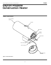
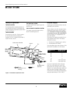
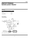
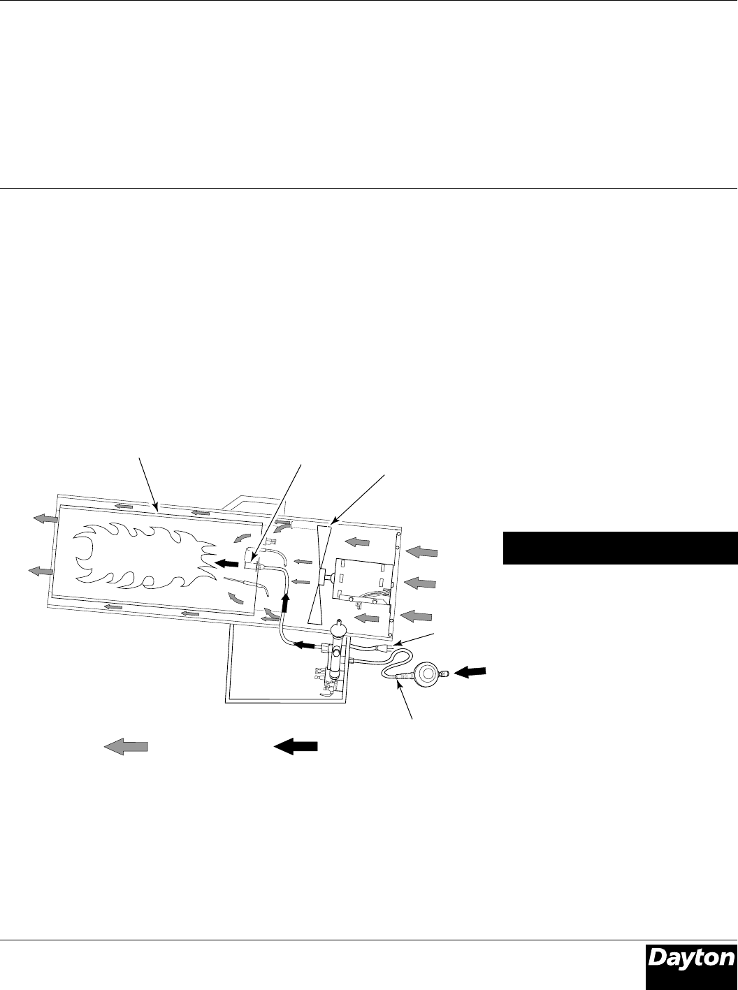
Air For Combustion
And Heating
Fuel
Combustion Chamber
Figure 3 - Cross Section Operational View
Clean
Heated
Air Out
(Front)
Hose/Regulator
Assembly
Nozzle
Fan
Cool Air
In (Back)
Power
Cord
THE FUEL SYSTEM
The hose/regulator assembly attaches to
the propane gas supply. The propane gas
moves through the automatic control valve
and out the nozzle.
THE AIR SYSTEM
The motor turns the fan. The fan pushes
air into and around the combustion
chamber. This air is heated and provides a
stream of clean, hot air.
Theory of Operation
Air for
Combustion and
Heating
Fuel
Propane Supply
Propane gas and propane tank(s) must be
provided by the customer.
Use this heater only with a propane vapor
withdrawal supply system. See Chapter 5
of the Standard for Storage and Handling
of Liquefied Petroleum Gas, ANSI/NFPA 58.
Your local library or fire department will
have this booklet.
The amount of propane gas ready for use
from propane tanks varies. Two factors
decide this amount:
1. The amount of propane gas in tank(s)
2. The temperature of tank(s)
The chart below shows the number of 100
pound tanks needed to run this heater.
Less gas is vaporized at lower tempera-
tures. You may need two or more 100
pound tanks or one larger tank in colder
weather. Your local propane gas dealer will
help you select the proper supply system.
The minimum surrounding air temperature
rating for each heater is -20°F (-29°C).
Temperature (ºF) Number of tanks,
at Tank 100,000 Btu/Hr
32° 2
20° 3
10° 3
0° 3
-10° Use Larger Tank
-20° Use Larger Tank
THE IGNITION SYSTEM
The spark transformer ignitor lights the
main burner.
THE AUTOMATIC CONTROL SYSTEM
This system causes the heater to shut
down if the flame goes out.