®
Dayton Installation, Operation, Maintenance and Parts Manual
Models 3E132 thru 3E134, 3E460 thru 3E462,
5VD57 thru 5VD66, 3VH34 thru 3VH37
E
N
G
L
I
S
H
Electric Shock Hazard.
Field wiring to the heater must be
connected and grounded in accordance
with national, state, provincial, local
codes and to the guidelines in the this
manual. In the United States refer to the most current
revisions to the ANSI/NFPA 70 Standard and in Canada
refer to the most current revisions of the CSA C22.1
Part I Standard.
17
WARNING
!
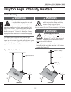
Electrical
Thermostat
Hot
Neutral
Exhaust Fan
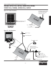
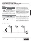
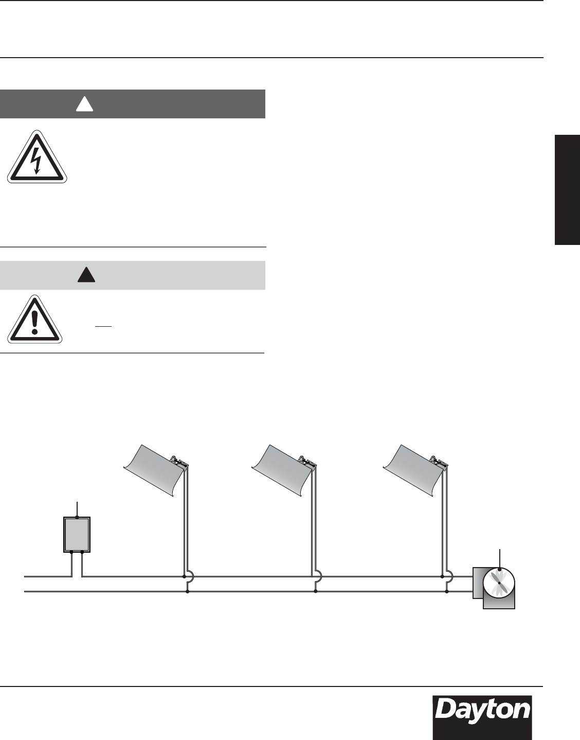
Figure 2.7 - Typical Field Wiring
Control systems are initiated by either 120 VAC or
24 VAC. The 120 VAC systems can be used directly
from a 120 VAC line. On 24 VAC systems, transformers
must be used to supply power of sufficient VA rating for
single or multiple connected installations.
Important! Proper grounding and polarity are essential
for heaters with spark ignition controls. If the system is
not properly grounded, it cannot determine the
presence of a flame and will lockout and shut off.
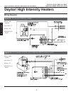
For wiring of controls on the unit see the wiring diagram
included on page 18. It is recommended that the
thermostat be installed on the hot side of a fused supply
line and have a sufficient ampere capacity rating for the
heater(s) it will control. The ventilation system may be
controlled separately from the heating system (consult
local codes) by the use of a humidistat that closes when
the humidity rises. The humidistat control should be
installed at roof level. For summer ventilation, a simple
on/off switch can be installed at the occupant level.
Avoid Equipment Failure.
Do not install 120V to a 24V control
system.
CAUTION
!


