


3
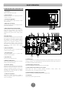
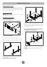
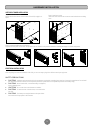
FRONT/REAR PANEL DESCRIPTION
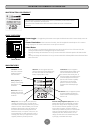
BASIC OPERATION
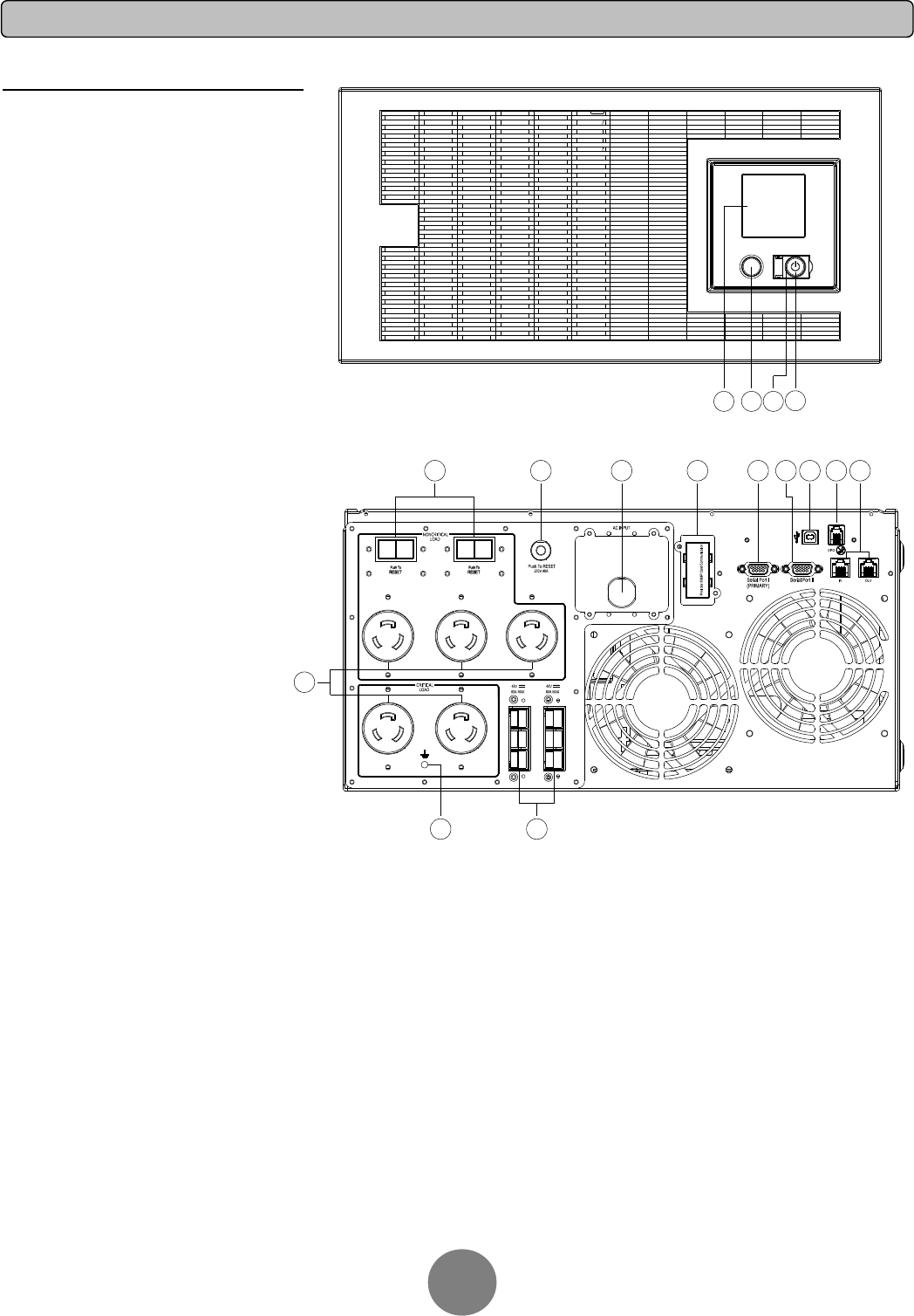
1. Power Switch
Master On/Off switch for the UPS.
2. Power on Indicator
Indicates the UPS is on and supplying power free
of surges and spikes.
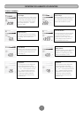
3. LCD Readout Toggle Button
Use to rotate through multiple screens of UPS
status information.
4. Multifunction LCD Readout
An illuminated digital screen that displays the UPS
power status information.
5. Battery Backup & Surge Protected Outlets
This unit provides a total of five outlets with battery
backup and surge protection. They ensure that
connected equipment will provide power to
equipment over a period of time, during a power
failure.
Critical /Non-Ccritical
It is possible to program the unit so that the outlet
block marked as “Non-Critical”, (3 ports), will stop
the supplying to connected equipment after a
certain period of time. This allows for additional
runtime for the equipment connected on the
outlets marked as “Critical”, (2 port). This allows
the creation of load priorities ensuring the critical
equipment is given priority under specific
circumstances.
6. Output Circuit Break
er
The circuit breaker serves to provide output
overload and fault protection.
7. Input Circuit Breaker
The circuit breaker serves to provide input
overload and fault protection.
8. Input Power Cord
Heavy-duty, extra long power cord.
9. SNMP/HTTP Network slot
Slot to install the optional SNMP card for remote
network control and monitoring.
10. Serial Port I (Primary)
Serial port I provides bi-directional communication
between the UPS and the computer. The UPS can
control the computer’s shutdown in case of an
emergency, and at the same time, the computer
can monitor the UPS and alter its various
programmable parameters.
11. Serial Port II (Secondary)
Serial Port II allows the UPS to initiate a
connected computer’s graceful auto-shutdown in
case of an emergency.
12
. USB port to PC
This is a connectivity port allowing communication and control between the UPS and the
connected computer. You should install the PowerPanel
®
Business Edition Agent software on
the PC/Server connected with the USB cord.
13. EPO (Emergency Power Off) Port:
Allows for an emergency UPS Power-Off from a remote location.
14. Surge Protected Communication Ports - RJ11/RJ45
These ports are used to protect standard RJ-45/RJ-11 based, (ADSL, LAN,
Phone/Modem-Lines), and cabling systems from surges.
15. Extended Runtime (XL) Battery Pack Connector
Provides a connection for additional CyberPower XL Battery Packs
16. Ground Stud
Use the Ground Stud to ground th
e UPS.
Expansion Port
240V,20A240V,20A
5
16
15
6 7 8 9
10 11
12
13 14
1
234
3