


60
Sequence of Operation
(Also Refer to Figures 9.7, 9.8, 10.3, 11.7)
Upon a call for heat from the room thermostat, the circulator is started.1)
If the differential pressure switch connected between the supply and return sees a pressure in excess of 5.1 ft 2)
w.c., it closes, allowing the start sequence to continue. If the switch does not see 5.1ft w.c. after 180seconds, the
boiler goes into lockout.
If the common and normally closed contacts on the air pressure switch are made, the inducer starts. 3)
The air pressure switch measures the difference between the combustion air pressure in the cabinet and the 4)
negative pressure generated at a venturi located in the inducer discharge. In this way it measures the air fl ow
through the boiler. If the pressure across the air pressure switch exceeds approximately 0.64” w.c., the switch will
close. If the air pressure does not close after 4 minutes of inducer operation, the boiler will go into lockout.
After the air pressure switch closes, current can pass through the normally closed supply water and fl ue gas 5)
safety limits to the ignition module, initiating a call for burner operation.
The ignition module generates an ignition spark and opens the valve. The presence of fl ame is detected through 6)
a separate fl ame rod. If no fl ame is detected after 10 seconds, the boiler will go into lockout. If the fl ame is proven
and this proof is subsequently lost at any point during the burner cycle, the boiler will attempt to re-light once, then
go into lockout.
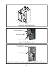
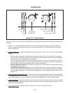
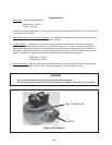
When responding to a call for heat, the boiler will attempt to maintain the target supply temperature selected by 7)
the Heating System Knob. The boiler does this by monitoring the supply temperature sensor shown in Figure
9.7/9.8
and modulating the input based on the difference between the current supply temperature and the
target supply temperature. Modulation is achieved by varying a 0-24VDC voltage across a coil on the gas valve
regulator (0V=minimum input).
If the supply water temperature exceeds the target supply temperature while the call for heat is present, the 8)
burner will shut down and the circulator will continue to run. The burner will relight when the supply temperature
drops below the target temperature.
If the supply temperature exceeds 221F (which should never happen unless there is a problem with the supply 9)
sensor), the manual reset supply water high limit will open.
If the condensate trap becomes blocked, the condensate level will rise to the point where it covers two electrical 10)
contacts: a contact connected to ground, and a contact in the fl ame rod lead. The condensate will complete an
electrical circuit between these two contacts, grounding out the unrectifi ed fl ame signal. This will be detected by
the ignition module as a loss of fl ame and result in a lockout.
If the fl ue temperature exceeds 248F, 11) the manual reset supply water high limit will open. This protects the PPs
venting from excessive temperatures.
When responding to a call for heat, combi boilers use exactly the same sequence of operation as heat-only 12)
models. When a combi boiler receives a call for domestic hot water (DHW), it responds as follows:
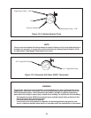
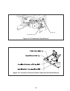
The fl ow switch shown in Figure 11.7a) detects a call for DHW draw when a hot water fi xture is opened having
a fl ow rate in excess of approximately 0.5 GPM.
The main control drives the 3-way diverting valve so that all boiler water fl ow is directed though the plate heat b)
exchanger.
If not already running, the circulator startsc)
The boiler fi res after going through the same start sequence described in steps (3-6) above. d)
The boiler monitors the exiting DHW temperature using the sensor shown in Figure 11.7. The boiler’s e)
microprocessor control determines the target boiler supply temperature that is needed to meet the DHW
demand and modulates the input accordingly.