


36
IX System Piping
CAUTION
Install boiler so that the gas ignition system components are protected from water (dripping, •
spraying, rain, etc) during appliance operation and service (circulator replacement, etc).
Operation of this boiler with continuous return temperatures below 86F can cause severe heat •
exchanger corrosion damage.
Operation of this boiler in a system having frequent additions of make-up water can cause severe •
heat exchanger damage.
Do not use toxic additives, such as automotive antifreeze, in a hydronic system.•
Before connecting boiler, make sure that the system is free of sediment, fl ux and any residual boiler •
water additives. Flush the system if necessary to ensure that these contaminates are removed.
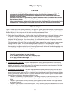
A. Standard Piping
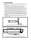
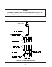
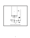
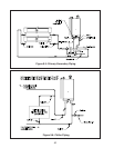
Figure 9.1 shows typical boiler system connections on a single zone system. Additional information on hydronic system
design may be found in Installation of Residential Hydronic Systems (Pub. #200) published by the Hydronics Institute in
Berkeley Heights, NJ. The components in this system and their purposes are as follows:
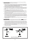
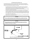
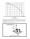
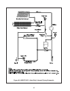
Relief valve (Included & Required)1) – Install the relief valve in the 3/4” connections on the top of the boiler as shown
in Figure 9.3. The relief valve shipped with the boiler is set to open at 30 psi. This valve may be replaced with
one having a setting at or below the Maximum Allowable Working Pressure (MAWP) shown on the ASME plate
attached to the heat exchanger. If the valve is replaced, the replacement must have a relief capacity in excess of
the Minimum Relief Valve Capacity shown on the rating plate.
Pipe the discharge of the relief valve to a location where water or steam will not create a hazard or cause property
damage if the valve opens. The end of the discharge pipe must terminate in an unthreaded pipe. If the relief
valve discharge is not piped to a drain, it must terminate at least 6 inches above the fl oor. Do not run relief valve
discharge piping through an area that is prone to freezing. The termination of the relief valve discharge piping must
be in an area where it is not likely to become plugged by debris.
DANGER
Pipe relief valve discharge to a safe location.•
Do not install a valve in the relief valve discharge line.•
Do not move relief valve from factory specifi ed location.•
Do not plug relief valve discharge.•
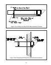
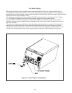
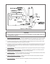
Circulator (Included & Required)2) – This boiler is equipped with a factory piped circulator, which is often the only
circulator required. Figure 9.2
is a performance curve for this circulator. Note that this curve is has been adjusted to
take into the account of all internal boiler piping. This performance curve therefore shows the amount of fl ow that
can be achieved at various heating system pressure drops.
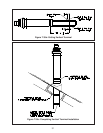
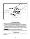
Throttling Valve or Flow Restrictor3) - This boiler is equipped with a differential pressure switch to prove that there is
fl ow through the boiler before allowing it to fi re. Reliable operation of this switch requires that there be a head loss
across the heating system of at least 5.1ft wc. In order to assure that this head loss will always be present, either a
throttling valve must be installed as shown in Figure 9.1 or the fl ow restrictor shown in Figure 9.4 must be installed.
Use the following guidelines to determine which device to use:
If the boiler is installed an a single zone system, or one having zone valves, install the throttling valve. At start-•
up, start with this valve fully open and then close it just enough to obtain reliable operation of the pressure
switch.
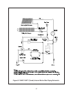
If the boiler is connected to a primary-secondary system (Figure 9.5), install the orifi ce in the supply tailpiece •
as shown in Figure 9.4.
If the boiler is connected to a circulator zone system, primary-secondary piping must be used. Install the orifi ce •
as shown in Figure 9.4.