


22
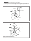
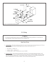
Sequence of Operation, Intermittent Ignition
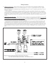
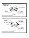
1) When the boiler is energized, 24 volts is immediately applied to terminals “1” (blue) and “4” (yellow) on the vent damper.
Assuming that there is no call for heat, and that the damper switch is in the “automatic” position, the damper will close.
2) A call for heat from the thermostat energizes relay coil 1R (the relay on the L8148E), causing contacts 1R1 and 1R2 to
make. Contact 1R1 starts the circulator. Contact 1R2 sends power to the high limit.
3) Assuming that the high limit is made, current will flow to pin terminal #2 (orange) at the vent damper and the damper will
open.
4) Once the vent damper is fully open, an end switch inside the damper will make, energizing pin #3 (red) at the damper. This
pin is connected through the damper harness to terminal “B1” on the L8148E. At this point in the operating sequence, 24
volts is present across “B1” and “B2”.
5) Under normal conditions, the flame roll-out switch and blocked vent switch are made. Voltage will therefore immediately
appear across the “24V” and “24V (GND)” terminals on the ignition module.
6) Upon application of voltage across the “24V” and “24V (GND)” terminals, the ignition module will start an ignition spark
at the pilot and apply 24 volts across the pilot valve (terminals “PV” and “MV/PV”).
7) Once the pilot is established, the pilot flame will act as a diode, converting the AC current at the electrode to a half wave
DC current at the pilot’s ground strap. This DC current flows through the boiler to the “GND (BURNER)” connection on
the ignition module. For the ignition module to recognize that a pilot flame is present, the DC current flowing into this
terminal must be in excess of approximately 1.0 uA.
8) Once the ignition module detects the presence of a pilot flame, voltage is applied across the main valve (terminals “MV”
and “MV/PV”), opening the valve and establishing main flame.
9) The way in which the ignition module handles failure to establish pilot or the loss of an already established pilot depends
upon the exact ignition module supplied with the boiler. For more information on module operation, consult the ignition
module instructions supplied with the boiler or the local Crown representative.
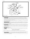
Safety Control Operation - Standing Pilot and Intermittent Ignition
High Limit - Interrupts main burner operation when the supply water temperature exceeds set point. Maximum allowable
temperature is 250°F. If the high limit opens, the vent damper will close if the damper switch is in the “automatic” position.
The circulator will continue to operate as long as there is a call for heat, regardless of the status of the high limit. Burner
operation automatically resumes when the supply water temperature falls below set point.
Blocked Vent (“Spill”) Switch - Automatically interrupts main burner operation in the event that flue gas spills from the draft
diverter opening. This switch is equipped with a reset button which must be pressed to restore normal burner operation. An
open blocked vent switch is indicative of a problem with the vent system. If the blocked vent switch opens, the cause of the
venting problem must be found and corrected by a qualified gas service technician before the blocked vent switch is reset.
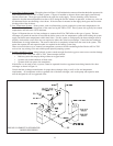
Flame Roll-out Switch - Automatically interrupts boiler operation when flames or excessive heat are present in vestibule. The
flame roll-out switch is a single use device which must be replaced by a identical switch in order to restore normal operation. An
open flame roll-out switch is usually indicative of a plugged heat exchanger. The cause of the flame roll-out must be found and
corrected by a qualified gas service technician, and the switch replaced with an identical one, before the boiler is returned to
operation.
20