


13
connected to the common venting system are not in operation.
a) Seal any unused opening in the common venting system.
b) Visually inspect the venting system for proper size and horizontal pitch and determine there is no blockage or
restriction, leakage, corrosion and other deficiencies which could cause an unsafe condition.
c) Insofar as practical, close all building doors and windows and all doors between the space in which all the appliances
remaining connected to the common venting system are located and other spaces of the building. Turn on clothes
dryers and any appliance not connected to the common venting system. Turn on any exhaust fans, such as range
hoods and bathroom exhausts, so they will operate at maximum speed. Do not operate a summer exhaust fan. Close
fireplace dampers.
d) Place in operation the appliance being inspected. Follow the lighting instructions. Adjust thermostat so the appliance
will operate continuously.
e) Test for spillage at the draft hood relief opening after five (5) minutes of main burner operation. Use the flame of a
match or candle, or smoke from a cigarette, cigar, or pipe.
f) After it has been determined that each appliance remaining connected to the common venting system properly vents
when tested as outlined above, return doors, windows, exhaust fans, fireplace dampers and any other gas-burning
appliances to their previous condition of use.
g) Any improper operation of the common venting system should be corrected so the installation conforms with the
National Fuel Gas Code, ANSI Z223.1. When resizing any portion of the common venting system, the common
venting system should be resized to approach the minimum size as determined using the appropriate tables in Part 10 of
the National Fuel Gas Code, ANSI Z223.1.
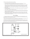
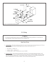
VII Gas Piping
Gas piping to the boiler must be sized to deliver adequate gas for the boiler to fire at the nameplate input at a line
pressure between the minimum and maximum values shown on the rating plate. For more information on gas line sizing,
consult the utility or Part 2 of the National Fuel Gas Code.
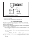
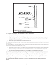
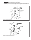
Figure 10 shows typical gas piping connection to the AWI/TWI boiler. A sediment trap must be installed upstream of all
gas controls. Install a manual shut-off valve outside the jacket and ground joint union as shown.
The boiler and its gas connection must be leak tested before placing the boiler in operation. When doing this, the boiler
and its individual shut-off must be disconnected from the rest of the system during any pressure testing of that system at
pressures in excess of 1/2 psi. When pressure testing the gas system at pressures of 1/2 psi or less, isolate the boiler from the
gas supply system by closing its individual manual shut-off valve.
11
FIGURE 10: GAS CONNECTION TO BOILER
* State of Massachusetts Requires Manual
Shut-off Valve to be “T” Handle Type
*