


20
Wiring Variations
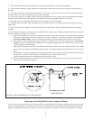
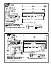
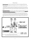
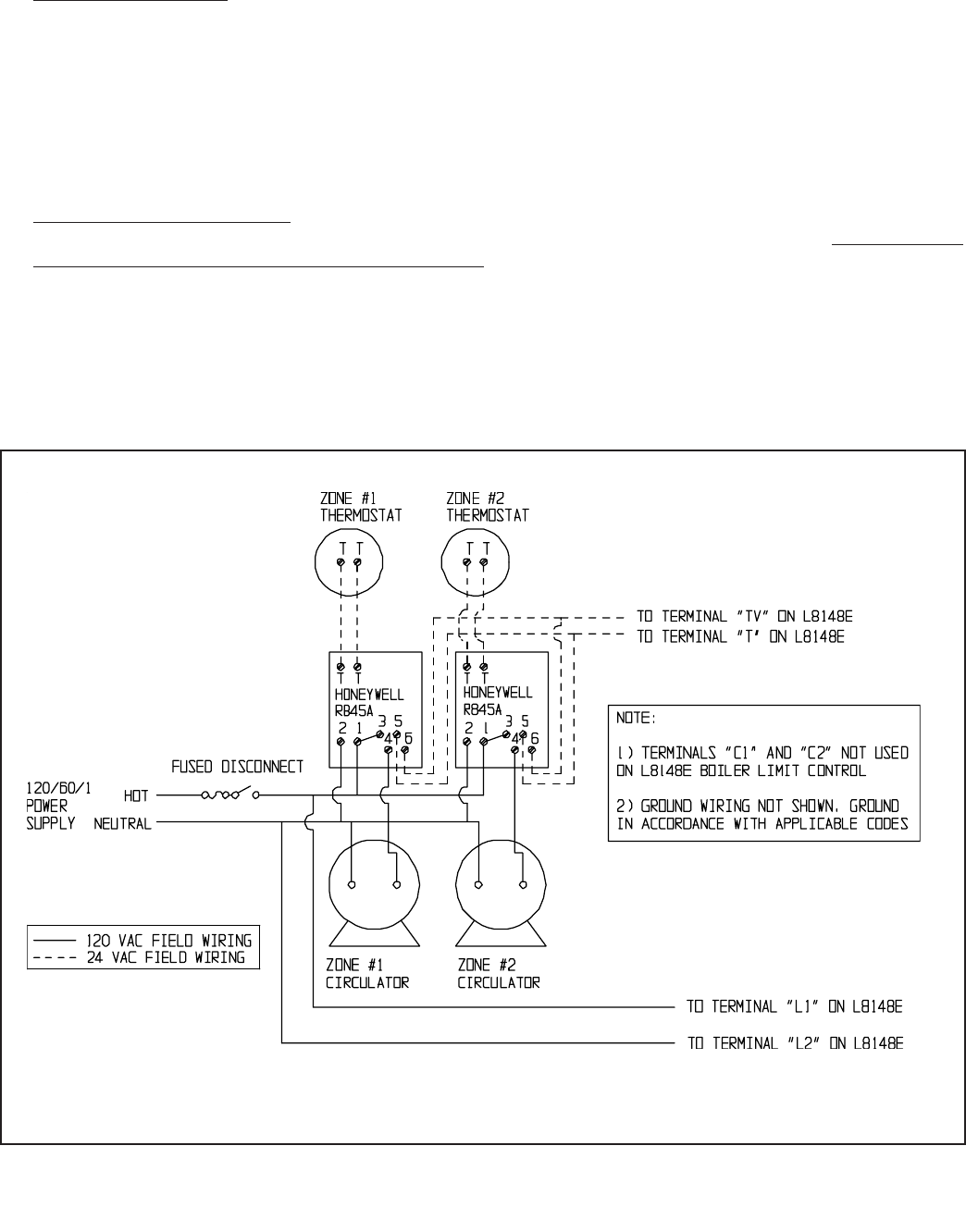
1) Multiple Circulator Zones – Figure 18 shows wiring for two or more circulator zones using Honeywell R845As. One
R845A is required for each circulator zone. Circulator terminals “C1” and “C2” on the L8148E are not used. A DPST
Honeywell RA832A may be substituted in place of the R845A using the “X” and “X” terminals in place of the “5” and “6”
terminals on a R845A.
A call for heat from any thermostat will energize the DPST relay in that zone’s R845A. When this relay is energized,
electrical continuity is created between terminals 3 and 4, energizing the circulator for that zone. At the same time, electri-
cal continuity is created between terminals 5 and 6 on the R845A, creating a current path from terminal “T” to “TV” on the
L8148E. Assuming that the supply water temperature is below the high limit setting, the normal ignition sequence will be
initiated.
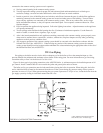
2) Multiple Zones using Zone Valves – Figure 19 shows wiring for multiple zones using Honeywell V8043F zone valves. This
wiring diagram may be used for other 24-volt zone valves as long as they are equipped with end switches. Do not attempt to
use the transformer on the L8148E to power the zone valves; use a separate transformer. Up to five V8043Fs may be
powered by one 48VA transformer, such as the Honeywell AT87A.
A call for heat from a given thermostat will result in the application of 24 volts across the TH and TR terminals on the
corresponding zone valve, energizing the zone valve motor. The zone valve opens and the end switch contacts are then
made. The end switches are connected in parallel with each other and to the “T” and “TV” thermostat connections so that
any zone valve that opens will also start the circulator and fire the boiler (assuming the high limit is not open). Zone valve
terminal TH/TR has no internal connection on the zone valve; it is merely a “binding post” used to connect two or more
wires.
FIGURE 18: CIRCULATOR ZONE WIRING USING HONEYWELL R845As
(FACTORY BOILER WIRING NOT SHOWN - SEE FIGURE 16 OR 17)
18