


7
INSTALLATION
Within five minutes the flash rate will change to approximately one second on and
one second off to indicate that the GPS Receiver has established a location “lock”.
Within 1 minute the flash color should be green to indicate good cellular coverage. If
you do not get the results above, refer to page 13, Section 13 – Troubleshooting
Confirming Proper Operation
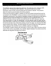
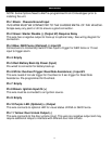
The Test wire (see wiring diagram) on the TRAKNET is for testing the internal
functionality of the hardware. Running tests with this wire grounded will not send
data to the call center. The user account does not need to be activated to run the
tests. Grounding the wire will start test mode function. If the wire is not removed
from ground the unit will remain in the test mode for 5 minutes and then return to
normal operation. To start the tests again you must ground the test wire again. If
you want the TRAKNET to function normally after testing, remove the test wire
from ground and tape the end to prevent the device from going into test mode
during normal operation.
Remember that the TRAKNET will remain in the test mode for only 5 minutes at a
time and you will need to cycle the test wire to re-enter the test mode. The
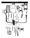
TRAKNET interface circuits are all pre-wired in the cable harness. Table 1 also
shows the wire colors associated with the input and output circuits. The digital
outputs are provided to switch optional external devices. Each can sink 1 amp at 35
volts. The outputs are voltage protected so they can sink current from inductive
loads. If the individual sink current is allowed to exceed 1 amp, the outputs could be
damaged. The digital inputs are triggered by a contact closure or short of less than
100 ohms from the contact to ground on their inputs.