


10
WIRING
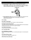
Pin 12 Orange: Alarm Trigger (-) Default* or Door Open/Close Input #1
A. Alarm Trigger*: Triggers alarm input of tracking device if received a negative
input for 15 seconds or longer. This is connected to the negative siren output, if
alarm has positive siren output use a relay to convert to negative.
B. Door Open/Close Input :This unit can be programmed for monitoring of door
open and close. This configuration must be program see dealer for
programming instructions.
Pin 13: Empty
Pin 14 Red: 12 Volts Input
This wire is the main power lead. It requires 12 volts constant power.
Pin15 Black: Chassis Ground Input
THIS WIRE MUST BE CONNECTED TO THE CHASSIS METAL OF THE VEHICLE.
Scrape away any paint or dirt to ensure a good connection.
Pin 16 Black Ground Input
This wire is ground input from the back up battery.
Pin 17 Gray (Not Used)
Pin 18 White/Brown (-) Output
This wire can be programmed to be a ½ second pulsed output or a 3 second pulsed
output.
Pin 19 Green/Yellow (-) Input
Ground this wire to trigger start up test on unit
PIN 20 White/Yellow (Not Used)