


Page 2
INTRODUCTION
THIS IS A GAS-FIRED, DRAFT INDUCED, POWER DEPENDENT, DIRECT VENT WALL FURNACE;
THAT WILL OPERATE SAFELY AND PROVIDE AN EFFICIENT SOURCE OF HEAT WHEN
INSTALLED, OPERATED AND MAINTAINED AS RECOMMENDED IN THESE INSTALLATION AND
OPERATING INSTRUCTIONS, LOCAL CODES AND THE LATEST EDITION OF ANSI Z223.1/NFPA54
OR IN CANADA CSA B149.1. READ THESE INSTRUCTIONS THOROUGHLY BEFORE INSTALLING,
SERVICING, OR USING THE APPLIANCE. IF YOU DO NOT UNDERSTAND ANY PART OF THESE
INSTRUCTIONS CONSULT LOCAL AUTHORITIES, OTHER QUALIFIED INSTALLERS, SERVICE
AGENCIES, THE GAS SUPPLIER OR THE MANUFACTURER.
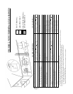
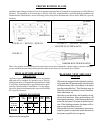
SPECIFICATIONS AND DIMENSIONS
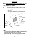
Your Direct Vent Wall Furnace is shipped complete in one carton. This carton contains the furnace, installation
and operating instructions, ball-valve w/flex connector, wall thermostat, 20’ wire, insulated staples, window
enclosure panels, caulking, weather stripping, and support brackets.
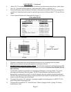
The State of Massachusetts requires that installation and service of a gas
appliance be performed by a plumber or gas fitter licensed in the
Commonwealth of Massachusetts.
For bedroom window installation, the State of Massachusetts requires two or more operable
windows in the bedroom that are in compliance with 780CMR, Massachusetts Building Code.
CABINET
MODEL INPUT GAS TYPE MAX. WALL MIN. WALL
NO. BTU/HR. WIDTH DEPTH HEIGHT CONN. GAS Thickness Thickness
WOW253 20,000 BTU 14-3/8” 28-3/16” 17-1/8” 3/8” NAT. 18” 4”
365 mm 716 mm 435 mm 458 mm 102 mm
WOW254 20,000 BTU 14-3/8” 28-3/16” 17-1/8” 3/8” L.P. 18” 4”
365 mm 716 mm 435 mm 458 mm 102 mm
WOW403 40,000 BTU 25” 22” 17-1/8” 3/8” NAT. 18” 4”
635 mm 559 mm 435 mm 458 mm 102 mm
WOW404 40,000 BTU 25” 22” 17-1/8” 3/8” L.P. 18” 4”
635 mm 559 mm 435 mm 458 mm 102 mm
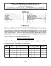
Introduction……………………………..... 2
Specifications and Dimensions………...….. 2
Safety Rules…………………………….. 3
Location................................................... 5
Clearances………………………………. 6
Installation………………………………. 5 - 11
Lighting Instructions……………………... 12
Proper Burner Flame................................. 13
Burner Orifice........................................... 13
Gas Conversion......................................... 14
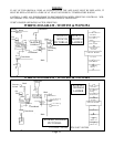
Wiring Diagram…………………………... 15
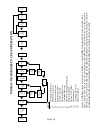
Sequence of Operation............................... 16
Maintenance Instructions............................. 17
Removing Main Burner..............................18 - 19
Removing Combustion Tube Assembly.......20 - 21
Trouble Shooting…………………..…... 22 - 23
Parts Drawing…………………………...25 - 26
Parts List………………………………...25 - 28
Warranty………………………………..... 29
CONTENTS