


Version 1.0b
31
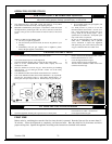
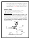
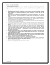
NOVA mV SET-UP GUIDE
The following information is provided to assist in the set-up of the 820 NOVA mV control valve. A certified
professional should install, perform conversions, and verify the proper operation of all Country Flame gas
appliances. If there are any questions, please contact a local authorized dealer or Country Flame direct for
assistance.
1. Bleed all air from gas lines before starting the system.
2. With the main burner in operation, adjust the inlet pressure regulator to supply gas to the appliance within the
design parameters of the appliance as dictated by site-specific requirements. (Typically 7”W.C. NG and
11”W.C. LPG.)
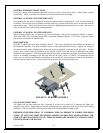
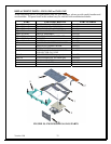
3. Make certain that the thermocouple and thermopile are fully inserted and tightened into their respective
holders in the pilot head. The thermocouple should be threaded into the valve hand-tight, and ¼ turn of the
wrench.
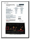
4. Verify that the system is wired properly and that all connections are clean and tight. Thermopile leads are to
be connected to the TPTH and TP connections of the main control valve. Thermostat and wall switch wires
are to be connected to the TPTH and the TH terminals of the main control valve.
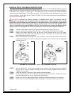
5. Turn the OFF/PILOT/ON control knob to the PILOT position and depress the knob while lighting the pilot
with a match or the piezoelectric igniter switch.
6. Continue to hold the OFF/PILOT/ON control knob in (depressed) until enough current is generated by the
thermocouple to engage the safety magnet. Remember: the Millivolt Plus system uses a thermocouple to
power the safety magnet and the Millivot system utilize power from a single thermopile to engage the safety
magnet.
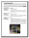
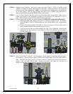
7. After the pilot flame has been lit for approximately three minutes and with only the thermopile wires
connected to the main control valve, measure the voltage across the TPTH and TP terminals. The open
circuit voltage should read between 500mV and 750mV. Adjust the pilot adjustment screw until the voltage
reading falls within these parameters. (Counterclockwise increases the voltage reading and clockwise
decreases the voltage reading.)
8. With the pilot flame adjusted properly, place a jumper wire between the TPTH and the TH connections. Take
a voltage reading across the TPTH and the TP terminals on the main control valve. This closed circuit
voltage should remain above 300mV.
9. Remove the jumper wire used in Step 8 that was connected from the TPTH and TH terminals and reconnect
the thermostat and wall switch wires to the same terminals. Take a closed circuit voltage reading as described
in Step 8. This closed circuit voltage reading should remain above 175mV.
10. Rotate the OFF/PILOT/ON knot to the ON position. The main burners should light.
11. Verify the operation of the thermostat and wall switch by cycling each individually. Observe the operation of
the main burner during the cycling of the thermostat and wall switch.
12. Rotate the OFF/PILOT/ON knob to the OFF position. Both the pilot flame and the main burner flames
should be immediately extinguished.
13. Refer to the wiring diagrams provided in this manual as needed.