


Version 1.0b
27
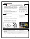
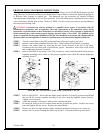
STEP 14 Open the gas supply and perform gas leak test. One of the best methods used to check for gas
leaks is soap bubbles. Soap bubbles are made by mixing liquid detergent with a little water and
shaking vigorously to create soap bubbles. Cover the gas pipe joint or valve component with
these soap bubbles. If soap bubbles grow in size or the bubbles are blown off the connection, a
gas leak exists. Make necessary repairs and retest until no change in soap bubbles is seen at
any joint or valve connection.
WARNING: DO NOT USE AN OPEN FLAME TO
CHECK FOR GAS LEAKS
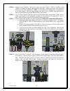
STEP 15 Re-light the appliance. Check the flame control operation.
NATURAL GAS CONVERSION
If conversion is required from propane fuel to natural gas fuel, follow the same 15 steps listed in the section
above using the proper Country Flame natural gas conversion kit. Adhere to the following:
NOTE: Conversion kits are to be installed by qualified service technicians.
NOTE: Do not install a kit IF conversion items are missing; check kit for all parts needed.
NOTE: A Torx T20 Tamper-Proof screwdriver may be ordered separately if needed.
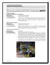
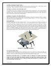
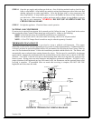
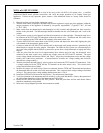
THERMOSTAT/FAN CIRCUIT
The Inglenook gas log control valve is pre-wired to accept a millivolt wall thermostat. This remote
thermostat can be used to turn the Inglenook gas log system on and off automatically. If additional airflow
is desired, purchase an optional Inglenook blower kit, part number IN-6200, directly from Country Flame or
one of its local authorized dealers. Follow the instructions provided with the blower kit. The blower will
automatically turn on when the heat sensing thermo-disc closes. The fan speed is controlled by the rheostat
speed control. Connect the wall thermostat to the terminal block on the control valve as shown in FIGURE
28 below. CAUTION: Label all wires prior to disconnecting them when servicing either the controls or the
blower system. Wiring errors can cause improper and dangerous operational conditions. ALWAYS verify
proper operation of the Inglenook gas logs, the control valve, the thermostat, and the optional blower after
servicing is complete. If operational issues are noted after servicing is complete, DO NOT USE THE
Inglenook until corrections are made.
1/16" to 1/8"
ON
OFF
ADJ
PILOT
IN
OUT
PILOT
ON
OFF
L
O
H
I
PIEZOELECTRIC
IGNITER
THERMOPILE
PILOT BURNER
ON/OFF SWITCH
TH
TP
TP TH
OPTIONAL (millivolt)
REMOTE RECEIVER
OPTIONAL (millivolt)
REMOTE SENDER
OPTIONAL (millivolt)
THERMOSTAT
IGNITER
THERMOCOUPLE
FIGURE 28: THERMOSTAT WIRING DIAGRAM