


Version 1.0b
30
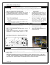
TROUBLE-SHOOTING GUIDE
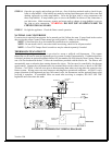
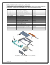
The 820 Nova millivolt control valve is available in three different configurations. They are the (1)
Millvolt Plus vented, or the (2) Millivolt Plus vent-free, or the (3) Millivolt systems.
The Millivolt Plus vented system is for use in direct vent appliances that require fast shut-off in the
even of a pilot flame failure. A thermocouple powers the safety magnet and a thermopile powers the
main control valve.
The Millivolt Plus vent-free system is used in conjunction with an ODS pilot. As with the vented
Millivolt Plus control valve, this valve uses a thermocouple to power the safety magnet and uses a
thermopile to power the main control valve.
The Millivolt system is used with gravity vented appliances where rapid shut-off is not necessary in the
event of a pilot flame outage. It uses a single thermopile to power both the safety magnet circuit and
the main control valve. A spill switch could be used in the safety magnet circuit of this system.
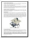
All NOVA control valves are fitted with a safety interlock device that prevents unsafe ignition of the
pilot burner after the ON/PILOT/OFF control knob is turned to the OFF position. All three of these
control valves can accommodate a wall switch, or a wall thermostat, or a remote control unit that can be
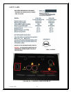
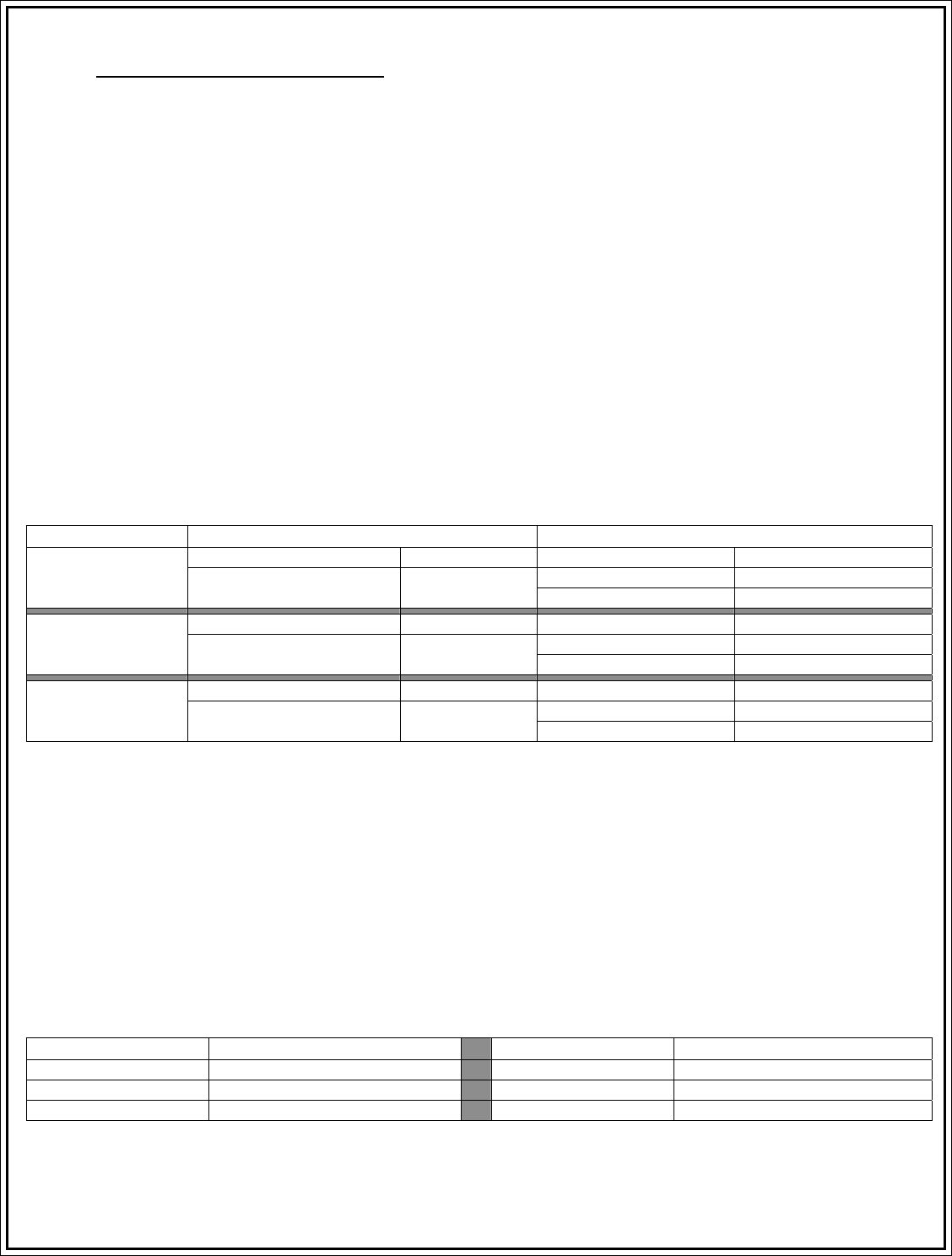
used to cycle the main control valve on and off. Following is the electrical data for the 820 Nova
millivolt gas control valve models:
VALVE TYPE MAIN CONTROL VALVE SAFETY MAGNET
Minimum Voltage 145 mV Hold-in current Less than 285mA
Drop-out current Greater than 125mA
NOVA mV Plus
Vented
Coil Resistance 2.25Ω±0.5Ω
Coil resistance 0.018Ω±0.003Ω
Minimum Voltage 145 mV Hold-in current Less than 200mA
Drop-out current Greater than 80mA
NOVA mV Plus
Un-vented
Coil Resistance 2.25Ω±0.5Ω
Coil resistance 0.018Ω±0.003Ω
Minimum Voltage 145 mV Hold-in current Less than 12mA
Drop-out current Greater than 4mA
NOVA Millivolt
Vented
Coil Resistance 2.25Ω±0.5Ω
Coil resistance 10.2Ω±0.05Ω
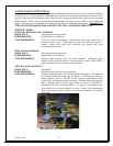
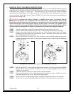
All millivolt control valve circuits are easily affected by electrical resistance. If enough resistance is
present in the appliances circuit, two things can occur. (A) Either the main control valve will work
intermittently and be unpredictable or (B) the main control valve will not work at all. There are several
areas where excess resistance can be found in the appliances circuit. In new installations, the
thermostat itself can be found to be the problem. Always use a thermostat rated for millivolt control as
they have been designed to minimize circuit resistance. The other area to check is the wiring itself.
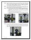
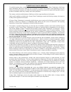
Wire gage plays an important part in wire resistance. The smaller the diameter of the wire and the
greater the length of the wire, the larger the circuit resistance will be. The table above provides
valuable information to select the proper wire that is used to connect to the main control valve. This
table refers to the total length of wire from the control valve out to the thermostat and back to the
control valve. All electrical connections must be tight, clean, and free from corrosion. Corrosion can
build up over time due to humidity problems so inspect wire connections on an annual basis.
WIRE SIZE MAXIMUM LENGTH WIRE SIZE MAXIMUM LENGTH
12 Gauge 150 feet 18 Gauge 40 feet
14 Gauge 100 feet 20 Gauge 25 feet
16 Gauge 64 feet 22 Gauge 16 feet