


6
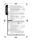
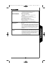
and light from the fixture. Also, if the fixture is in a shadowy location, it may think it
is always night time. The light shield/reflector can be used to block or channel light
to the photo sensor.
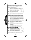
Step 1: Turn off the power at the main fuse/breaker box.
Step 2: Loosen, but do not remove, the threaded ring at the
top of the photo sensor.
Step 3: Slide the light shield under the threaded ring.
Step 4: Position the light shield/reflector so that it blocks
light to sensor or reflects light to the sensor,
depending on the problem you are having.
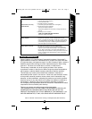
Step 5: Tighten down the threaded ring to hold the light
shield/reflector in place (Fig. 10).
Step 6: Turn the power back on.
Replacing the light sensor
Step 1: Turn off the power at the main fuse/breaker box.
Step 2: Loosen, but do not remove, the lens screws and retaining clips.
Remove the lens.
Step 3: Remove the bulb from the socket.
Step 4: Remove the reflector screw and remove the reflector.
Step 5: Remove the locknut from the outside of the light sensor.
Step 6: Disconnect wires from the light sensor one at a time.
Connect the new light sensor by:
• Connecting black sensor wire to the black supply wire (hot).
• Connecting red sensor wire to the black ballast wire.
• Connecting white sensor wire to the white supply wire
(neutral), white socket wire, and white ballast wire.
• Attach UL approved wire connectors (not provided) over all connections.
Step 7: Replace the locknut on the outside of the light sensor.
Step 8: Replace the reflector and reflector screw, install the bulb, and replace
the lens.
Step 9: Turn power back on.
Call for customer service and/or missing or damaged parts (800-334-6871)
ENGLISH
Fig. 10
MD42FLW_FLB 825-0132.qxd:MD Series 325-1432.qxd 5/28/08 8:27 PM Page 6