


5
attempt to use with other electrical fixtures! These connectors
are designed to withstand the temperature and voltage
requirements of this Cooper Lighting, LLC product only.
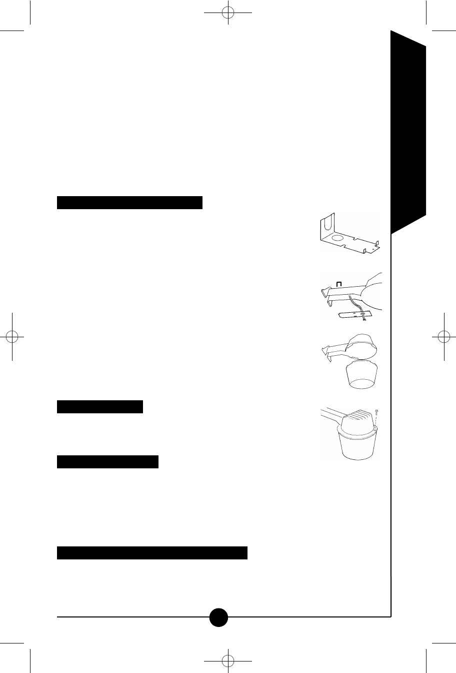
Step 2: Attach your ground supply wire to the fixture using the green
ground screw.
Step 3: Connect black fixture wire to black supply wire (hot). Secure with
wire nut (not included).
Step 4: Connect white fixture wire to white supply wire (neutral). Secure with
wire nut (not included).
Step 5: Be careful to connect the wires correctly. Make sure no bare strands
of wire extend from the wire nut or other approved wire connectors
(not included).
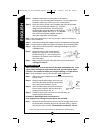
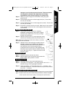
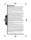
Attaching access cover and lens
Step 1: If your fixture is to be mounted to a standard
lampholder mounting plate, remove the U-shaped
knockout on the back of the cover (Fig. 6) using a
hammer and screwdriver.
Step 2: Attach the access cover (C) to the light fixture using
access cover mounting screws (D) provided (Fig. 7).
Note: Make sure all wiring is inside of the fixture arm before
the access cover is secured.
Step 3: Attach the lens to the housing by carefully lining up
the slots on the lens to the tabs on the housing.
Carefully insert the slots over the tabs, and twist the
lens clockwise until it locks into place (Fig. 8).
Locate the lens lock screw (F) in the hardware bag.
Place this screw in the screw hole located at the top
front of the fixture (Fig. 9). Tighten the screw to hold
the lens in place.
Installing the bulb
Step 1: Screw the bulb (J) securely into socket.
Step 2: Back the bulb out one or two turns, then screw bulb
back to insure proper position in socket.
Operating your fixture
Step 1: Turn on the power at the main fuse/breaker box.
Step 2: Turn power on to the fixture. Your fixture should come on for 1 – 4
minutes, then go off during daylight installation.
Step 3: To test your fixture, cover the light sensor for 1 – 3 minutes. Your
fixture should come on. Uncover the sensor, and your fixture should
turn off in 1 – 4 minutes.
Installing the optional light shield/reflector
Note: Sometimes fixtures are installed in locations that receive too much reflected
light. The photo sensor may have trouble telling the difference between daylight
Fig. 6
Fig. 7
Fig. 8
Fig. 9
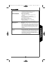
Call for customer service and/or missing or damaged parts (800-334-6871)
ENGLISH
MD42FLW_FLB 825-0132.qxd:MD Series 325-1432.qxd 5/28/08 8:27 PM Page 5