9
UVS33/36 Vent-Free Heaters
20002211
NOTE: 110/120 electric power is required to operate
blower (fan).
Be sure to leave sufficient excess wire in case minor
adjustments are required.
Any electrical rewiring of this fan must be
done by a qualified electrician.
Whether wiring directly to the fan junction box or into
the EB1 (electrical receptacle box, P/N ZA1200) first
ensure cable is secured using box connector.
Turn off all power before hookup.
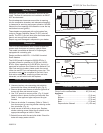
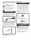
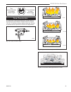
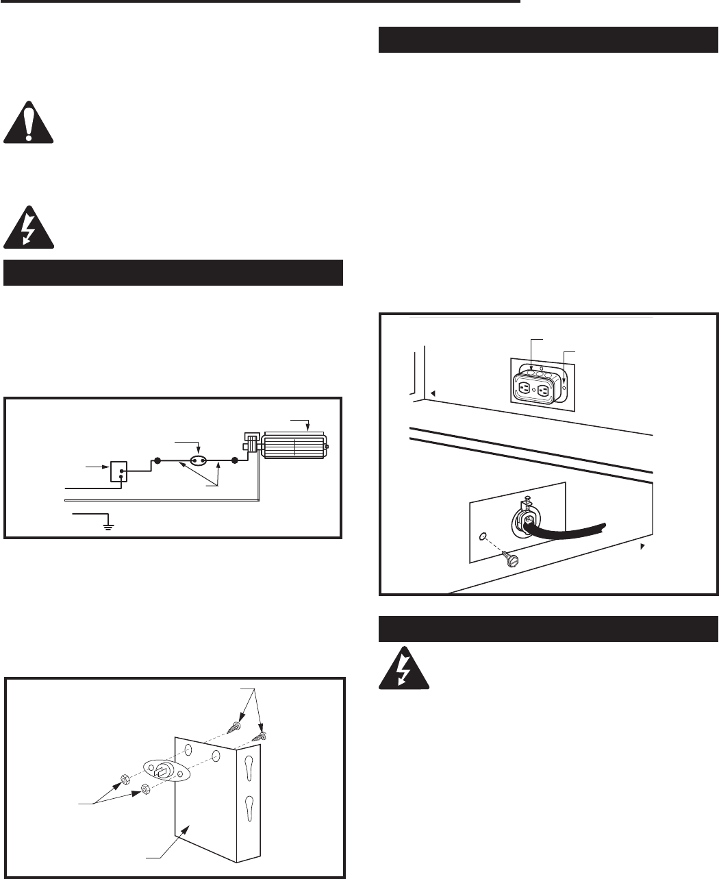
Hard (Direct) Wire Hook-Up
First connect ground wire to ground stud located on
the base of either box. Black wire from supply should
connect to the variable speed switch. Alternate speed
switch wire connects to temperature sensor. Alternate
lead from sensor connects to fan. Alternate fan con-
nects back to white supply wire. (Fig. 10)
FP394
WIRING DIAGRAM
11/20/96
Fig. 10 Wiring diagram.
FP394
Fan
Temperature
Sensor
Speed
Control
Black
White
Ground
Sensor Wire
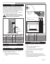
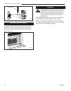
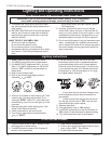
Remove sensor wire from bottom of heater. Remove
temperature sensor from FK24 wire leads. Attach male
coupler end of sensor wire to wire leads and opposite
end of sensor wire to temperature sensor. Attach tem-
perature sensor to left louvre bracket behind left side of
top louvre assembly with two #6 machine screws and
hex nuts. (Fig. 11)
FP1001
louvre bracket
uvs33
1/20/00 djt
Machine Screws
Hex Nuts
Louvre Bracket
FP1001
Fig. 11 Louvre bracket.
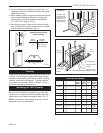
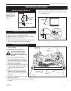
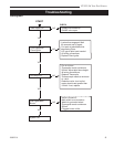
EB1 (Receptacle) Hook-Up:
1. Remove 2" knockout. Slide the electrical box back
plate into the back and bottom lances (clips) while
fitting the box connector into the knockout. Fasten
into place with fastening screws provided. (Fig. 12)
2. Connect the black positive wire to brass screw
(polarized side) of the receptacle. The white wire is
connected to the chrome screw. The ground wire is
connected to the green ground screw of the recep-
tacle. Fit the receptacle into the electrical box.
3. Screw the cover plate provided to the electrical box.
Label all wires prior to dicsonnection when servicing
controls. Wiring errors can cause improper and danger-
ous operation.
Verify proper operation after servicing.
Fan should come on within 10 minutes of ignition with
speed control in "ON" position.
Fig. 12 Junction box (EB-1) hook-up.
FP580
FP580
INSTA VENT FREE
EB1 JUNCTION BOX
11/18/97
Outside
Electrical Box
Front of Unit
Inside
Front of Unit
Retaining Screw
Remote Wall Switch
CAUTION: Do not wire millivolt remote wall
switch for gas heater to a 120v power sup-
ply. For lighting instructions, see Page 13.
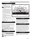
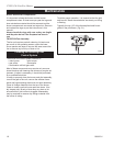
1. Thread wire through the electrical knockout located
on either side of unit. Do not cut wire or insulation
on metal edges. Ensure that wire is protected. Run
the other end to a conveniently located wall recep-
tacle box.
2. Attach wire to switch and install switch into recep-
tacle box. Attach cover plate to switch.
3. Connect wiring to gas valve. (Fig. 13)


