


20008845
11
LG378
UVLX24 logs
12/22/04 djt
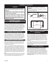
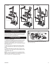
Fireplace Screen
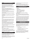
The fireplace screen must be in place when the appli-
ance is operating, and unless other provisions for com-
bustion air are made, the screen must have openings
for the introduction of combustion air.
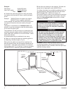
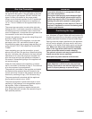
5. Remote wall switch
(RN and RP models only)
1. Thread wire through the electrical knockout located
on either side of the fireplace. Do not cut the wire or
insulation on metal edges. Ensure that the wire is
protected. Run the other end to a conveniently-located
wall receptacle box.
2. Attach the wire to the switch and install the switch
into the receptacle box. Attach the cover plate to the
switch.
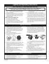
3. Connect the wiring to the gas valve. One wire con-
nects to the ‘TP/TH’ terminal; the other attaches to the
‘TH’ terminal. (Fig. 10)
NOTE: If any of the original wire as supplied with the
appliance must be replaced, it must be replaced with a
wire of at least a 60°C temperature rating.
PILOT
ON
OFF
L
O
H
I
751/Honeywell valve wiring
968lUVHL
7/27/98
Control Knob
Piezo Ignitor
Hi/Lo Knob
To Wall Switch
751
Fig. 9 Connecting a wall switch to the valve terminals.
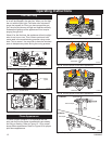
(UVLX-R Series only)
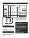
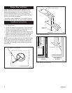
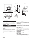
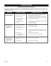
UVLX18
UVLX24
UVLX30
Fig. 8 Positioning logs on grate assembly.
LG376
LG378
LG380
LG376
UVLX18 logs
12/21/04 djt
LG380
UVLX30 Logs
12/22/04 djt